Annin Robotics Community
- Peter Kappes@pkappes· 53 viewsin General Discussion
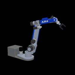
First AR4 integration tests from Ares.
Thanks for sharing!
Loading comments…
Good evening,it has been some time I put my AR4 MK3 together and only now start trying to make some actual use of it rather than playing around...
I changed the gripper now to the pneumatic one to have a bit quicker reaction times and stronger grip but ran into some issues when programming it in the HMI. The manual does state to use:
Out On = 8
and
Out Off = 8
to open and close the gripper. This seems not to be working though. Unless I am mistaken, it should be:
Set 5v Output # 8 = 0
and
Set 5v Output # 8 = 1
Tried this and it works well ;) ... 8 is the pin on the Nano as wiring is done the same as in the manual...
On an additional note, I had to remove the diode as it cut out my power supply . It seems to work without just fine without.
Hope this helps someone else too.
All the best,
Frank
Loading comments…
Low-Frequency Interference Caused by Ground Loops
Hello everyone. I am using a stepper motor with an encoder (https://www.oyostepper.com/category-36-b0-Stepper-Motor-w-Encoder.html). To improve noise immunity, I connected the shield of the encoder signal cable to the ground at both the encoder end and the driver end. However, this has caused occasional extra pulse counts during low-speed operation, leading to slight, jittery fluctuations in the coordinates displayed on the CNC screen.
Using an oscilloscope to examine the A/B signals, I observed low-frequency interference—around 50 Hz—superimposed on the waveforms.
According to the technical documentation I've consulted, grounding both ends creates a "ground loop." The potential difference between the two ground points causes a circulating current to flow through the shield, which then couples into the signal lines.
The interference disappeared after I switched to a single-ended ground connection. I would like to ask: should the encoder cable shield be grounded at one end or both ends? And if it should be grounded at only one end, which side is preferable—the encoder side or the driver side?
Thank you.
make J5 and J6 move together on a custom robot while keeping the kinematics accurate
Hi Chris, Hi everyone
I am currently designing a robot that has bevel gear for j6, the issue is that the bevel gear creates a differential relationship between the joint angles (j5 and j6). When j5 moves, j6 will move also.
Can you please help with a modified code Chris. How difficult it is to modify the Arduino IDE code?
Thanks.
Loading comments…