

Question about the AR4-MK3 Calculation Sheet
Hi everyone, I'm build a robot arm from scratch and the AR4-MK3 has served as a great source of inspiration. I've been playing around with the calculation sheet a while and I wonder why there are some offsets values for the joint angle in the DH Table. See the attached picture.
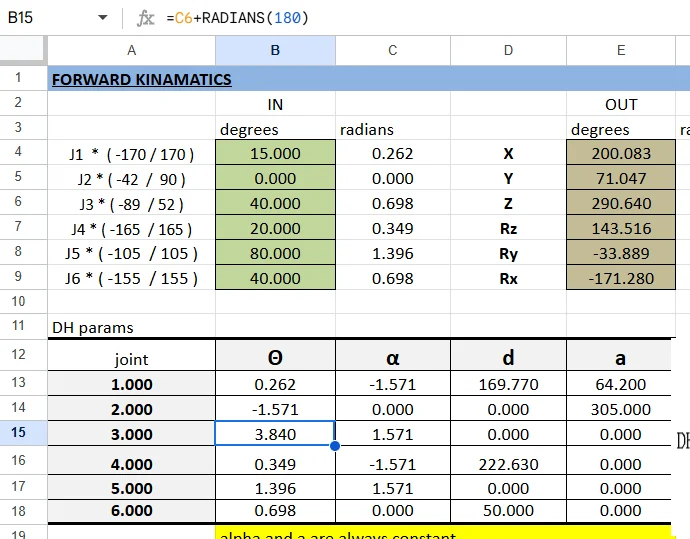

In standard DH, each joint variable θᵢ is defined as the rotation about zᵢ₋₁ that aligns xᵢ₋₁ with xᵢ. Because this is a geometric convention, the θ values you end up using depend on how the real robot’s mechanical zero positions are defined relative to the abstract DH coordinate frames.
Why θ₂ has an offset of –90°
- The DH frame assignment often requires that the x-axis of joint 2 be perpendicular to the z₁-axis.
- But mechanically, in many 6-axis arms (like PUMA or AR-series), the second joint’s “zero” is not perpendicular — instead, the arm link points straight forward or upward.
- To reconcile this, you add a –90° shift so that when θ₂ = 0 in software, the DH transform lines up with the physical link orientation.
- In other words, it’s a bookkeeping correction to make the DH chain’s kinematics match the real arm’s geometry.
Why θ₃ has an offset of +180°
- When assigning DH frames, the orientation of the 3rd joint axis (z₂) relative to the 2nd frame (x₂, y₂, z₂) sometimes ends up “flipped” compared to the physical robot’s elbow joint.
- If you didn’t add an offset, the mathematical model would give the elbow pointing backward instead of forward.
- By applying a +180° shift, you rotate the axis so that the forward kinematics correctly reflect the real robot’s link orientation.
- This ensures consistency: positive θ₃ motion corresponds to the real elbow motion direction, and the wrist lines up properly.
General Rule
Offsets like –90° or +180° aren’t arbitrary — they come from:
- DH convention requirements (xᵢ must be along the common normal, zᵢ along the joint axis, etc.).
- Robot manufacturer’s zero position definitions.
(Mechanical “zero” doesn’t always line up with the mathematically convenient zero.)
So these offsets are essentially “calibration constants” that make the standard DH model match the physical robot’s actual geometry.

Chris Annin Thank you for your reply! Could I also follow up with a picture of my current kinematics diagram for you to have look at? I want to make sure that the diagram match the DH parameters table.
If you want to email that to me I'll take a look and try to have a look at it as soon as I have a few min. info@anninrobotics.com If you are building a 6 axis robot and you are tying to use the AR software to control it my best advice is to leave most of the DH params as they are and only modify the link lengths in the 'd' and 'a' columns.
Chris Annin That would be amazing, thank you! FYI, I'm trying to build my own software too, so I'm interested in how you applied the geometric method to calculate the joints and EE position and orientation for the AR4.