

AR4 Round 2 : A summer project
Hi all,
I build an AR3 before and converted it to an AR4 later.
See my original post here:
This summer, my nephew and a friend are looking for an introduction to machining and robotics.
So with the help of Lael (16) and Benjamin (15), we are going to build an AR4 by machining all the pieces. The goal is to complete the machining and the build in 2 weeks - an ambitious goal !
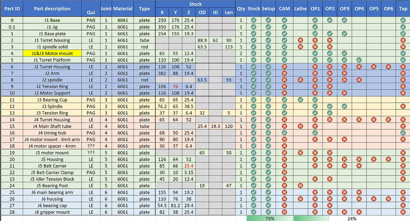
To get the project started on a good track, I have prepared the material inventory and most of the CAM work:

My goal is to machine the parts for J1 before their arrival in July in order to give them a head start.

Next is J1 Base Plate, very similar machining than J0 Base:
J1 Base Plate OP1, we machine the key features

J1 Base Plate OP2, re-using the jig from J0 Base, we hold the part upside down and machine the hat:

This is a bit more tricky because the 4 M8 bolts are in the way
First we machine 3 areas clear of the bolts:
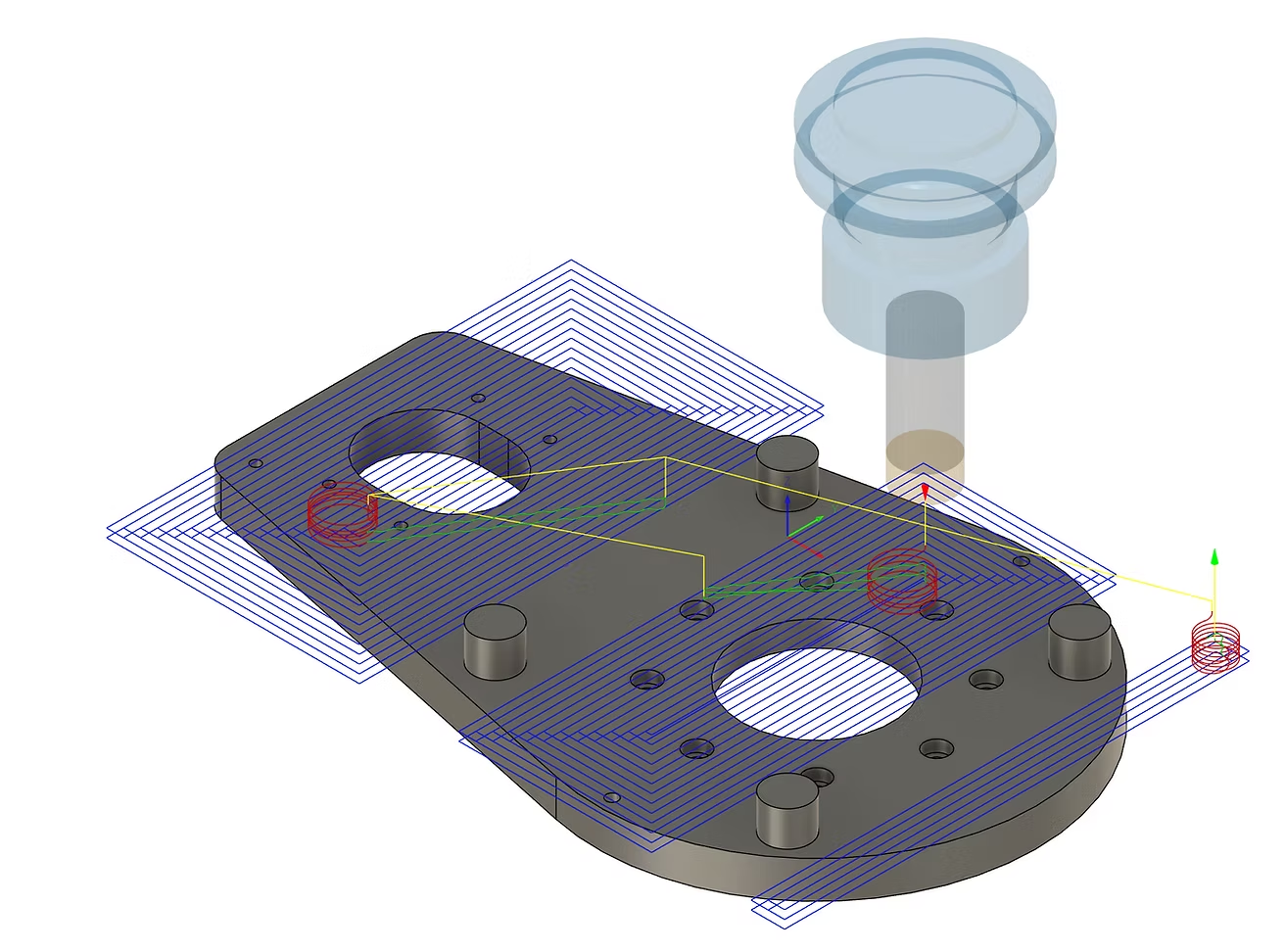
then remove 2 bots and machine that area:
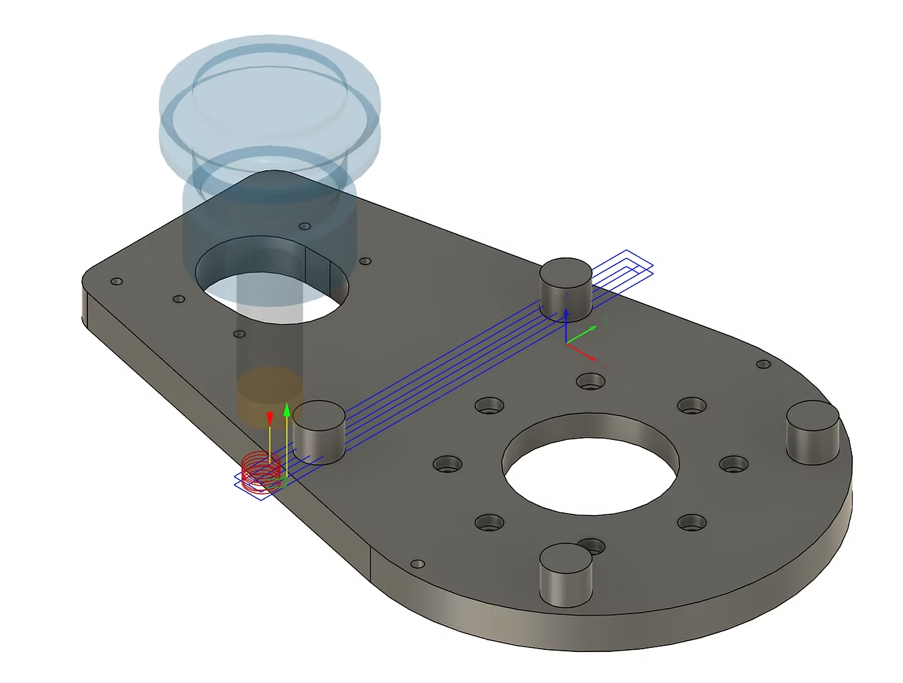
then swap the bolts and machine the last area:
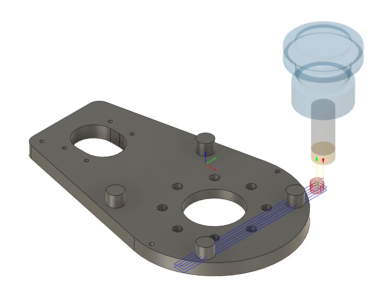
After some taping, J1 Base Plate is done
Since this is my 2-1/2th AR4 I'm building (IAR3 then converted to AR4 back in 2020, see post here: https://anninrobotics.com/community/robot-builds/ar3-in-florida ), I am acutely aware of the difficulties to wire everything in the tight controller box.
So I took the liberty to modify the box, since it is now detached from the machined base and enlarged it by 30mm in both length and width. Of course that meant enlarging as well the tray and the lid. I took some hum creative liberties with the lid design:
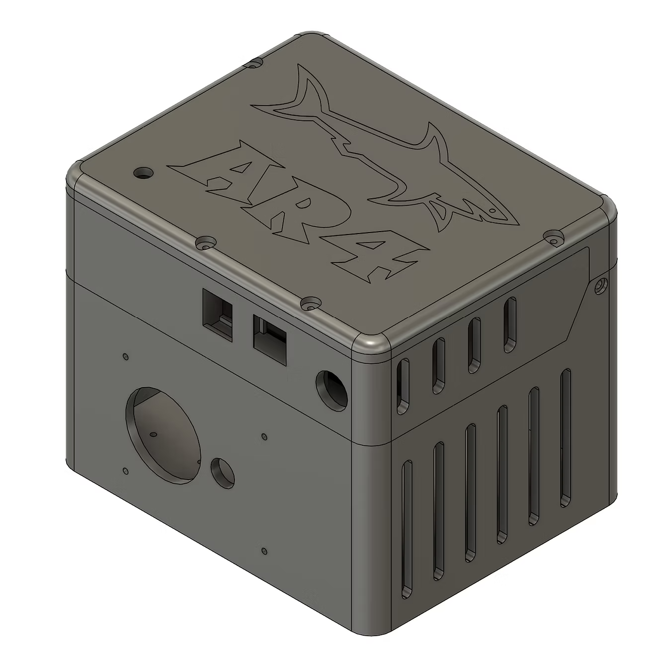
enlarged controller box
Here is the box printed and connected to the base with 2 M4 bolts:
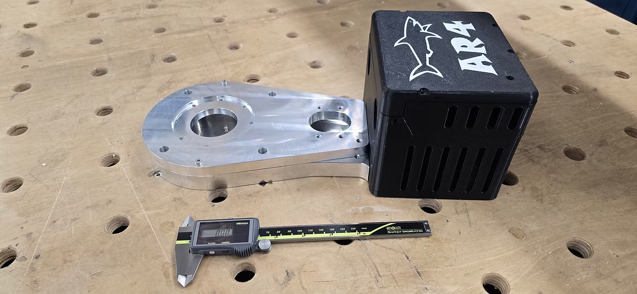
I like big controller box and I cannot lie...
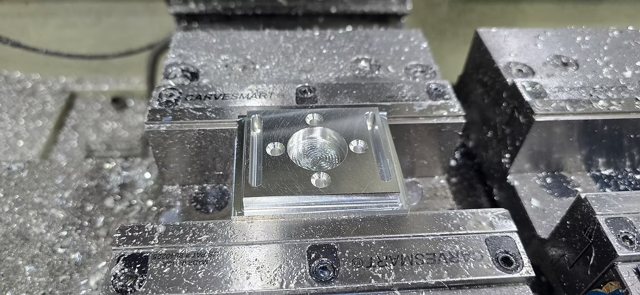
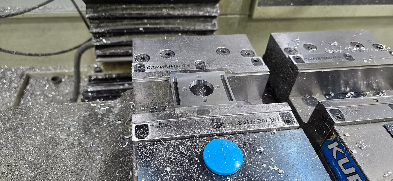
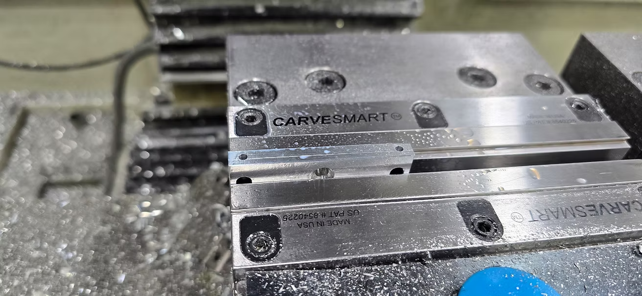
I'm skipping J1 Turret housing and spindle for now because they are mostly lathe part and Lael is already proficient in lathe work and this will be a great gateway for the first CNC operations.
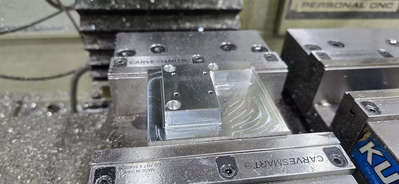
Moving down the list, I machined the turret platform.
OP1 is very similar to the previous parts where we face up, machine the contours, drill holes and chamfer the edges:
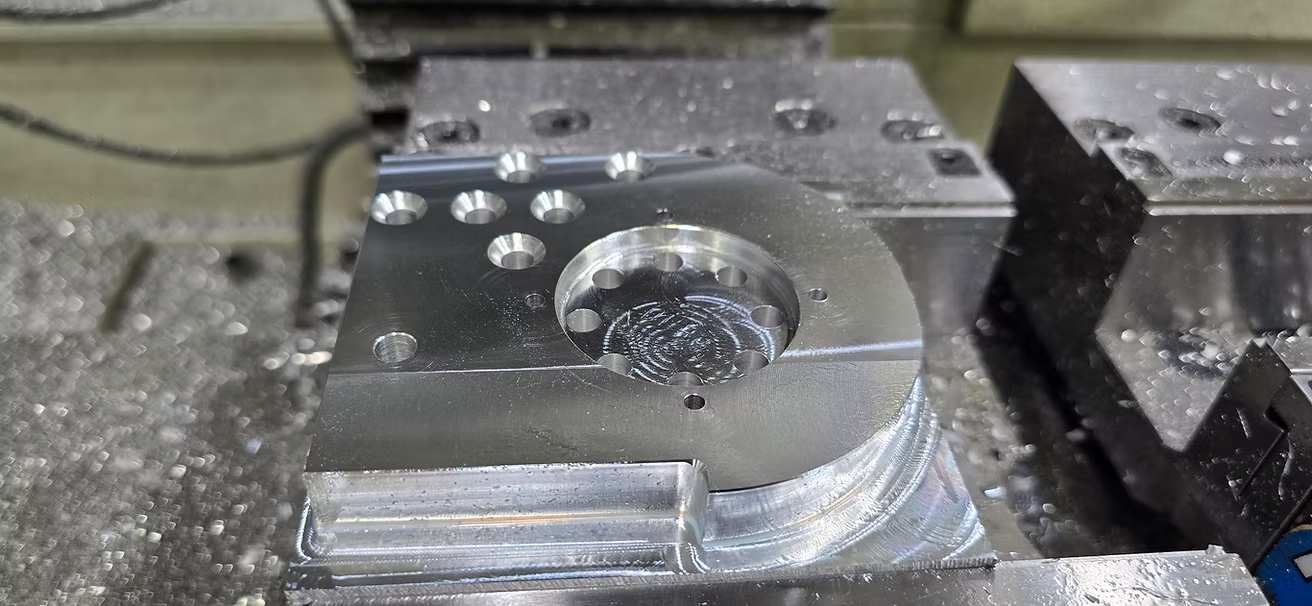
OP2 is done is 2 steps: decking the hat with a facing operation, probing one of the hole to run the chamfering:
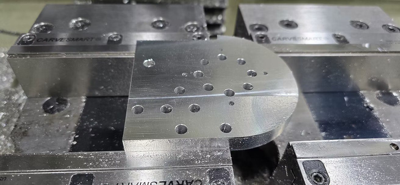
Then OP3 is drilling but we take advantage of holding the part in this orientation to clean the corner, in OP1 that corner was limited to the radius of the contouring tool (in my case a 1/4in end mill)
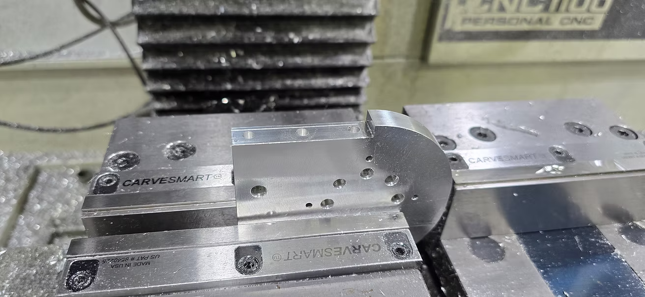
In this orientation, we clear the corner, limited now by the corner radius of the endmill:
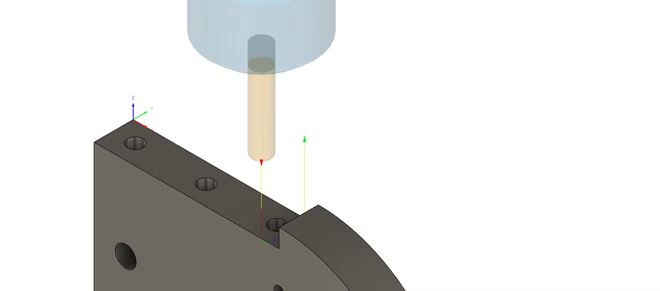
cleaning up the corner left by the previous contouring operation
And finally the 2 holes in the last operation:
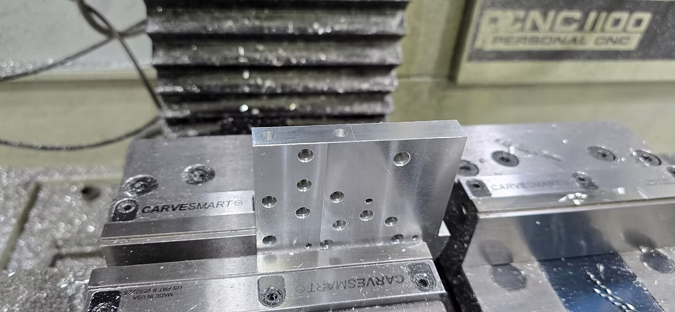
With that J1 Turret platform is down and I have enough parts to let Benjamin and Lael start the machining and the build. Future updates will be around end of July with them, stay tuned, J2 Turret housing, J2 Arm and J5 housing are very interesting form a machining stand point.
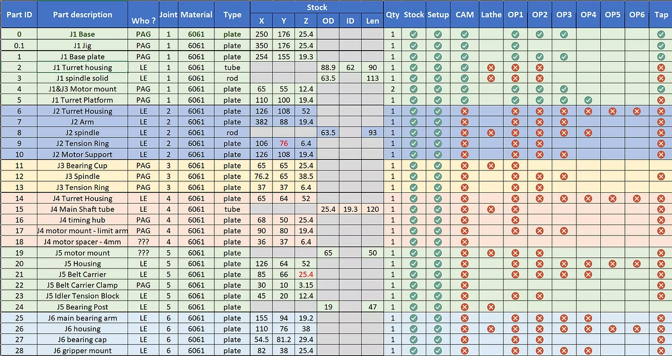
As always, thanks Chris for your amazing design, your support and your help inspiring the next generation of machinists, robotic engineers and all-in-all makers !
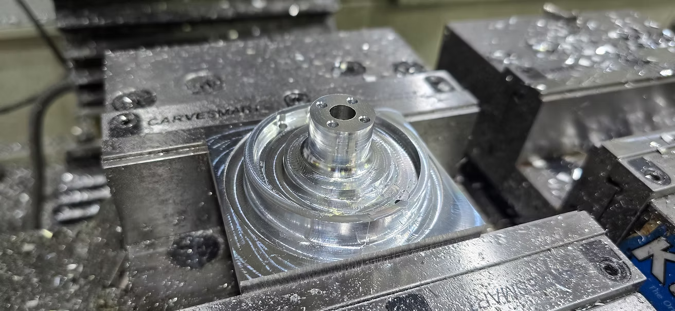
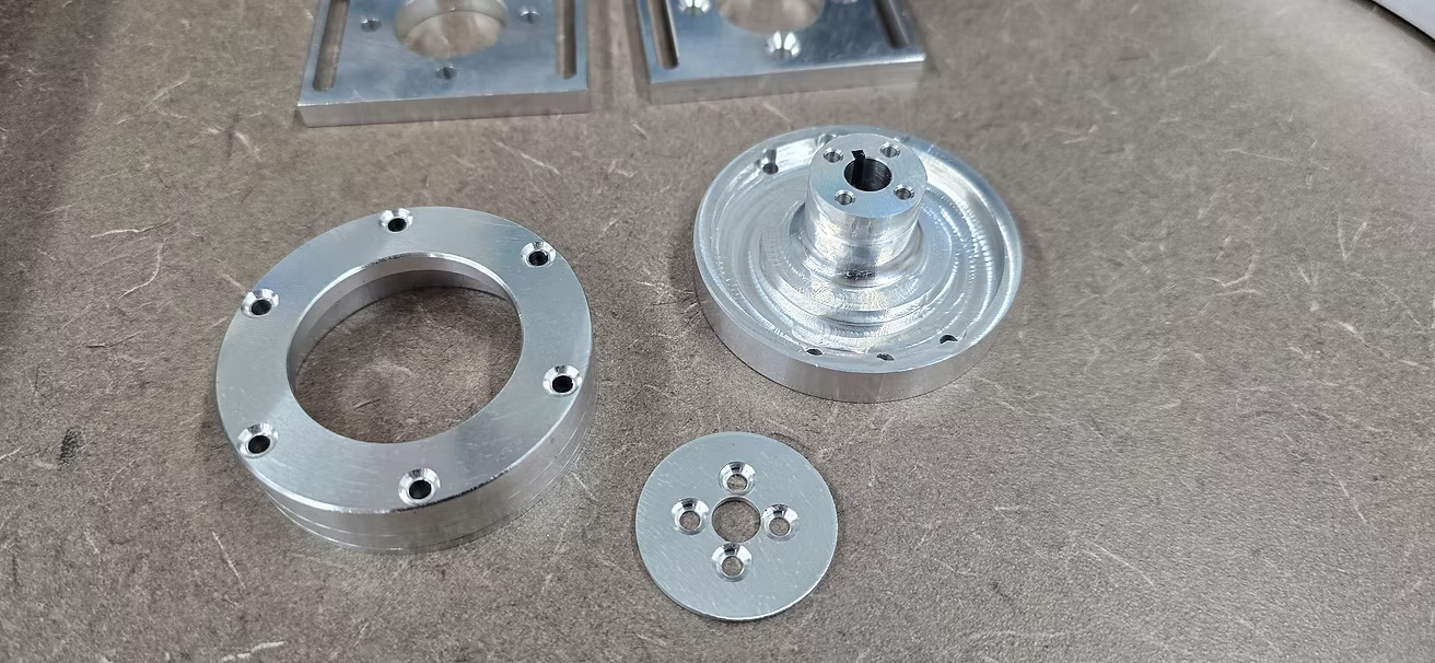
Moving on to J3 spindle, a pretty straight forward part with OP1 machining most of the features. The only trick here is the order of operations, you have to drill the 6 holes on the periphery before machining the recess
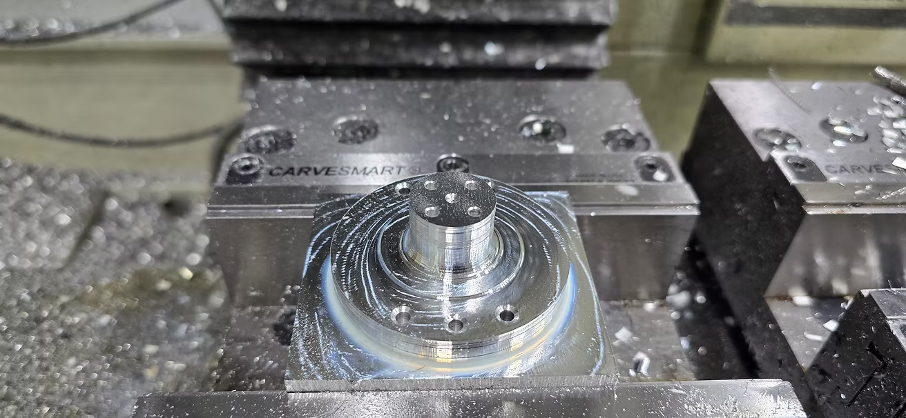
drill before machining the pocket
Then OP2 to remove the hat
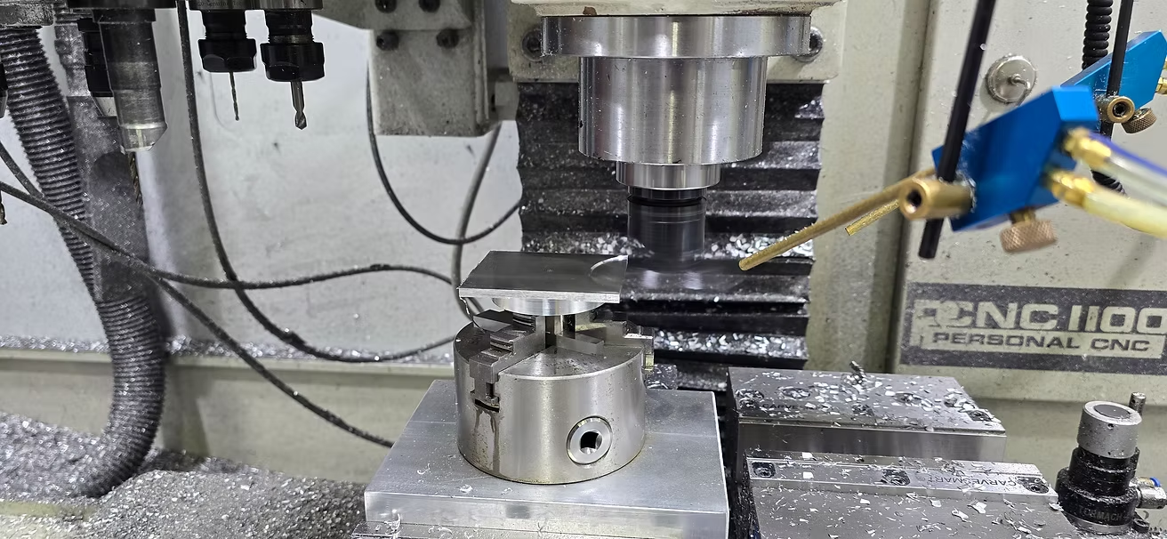
And finally OP3 to drill the set screw hole on the spindle:
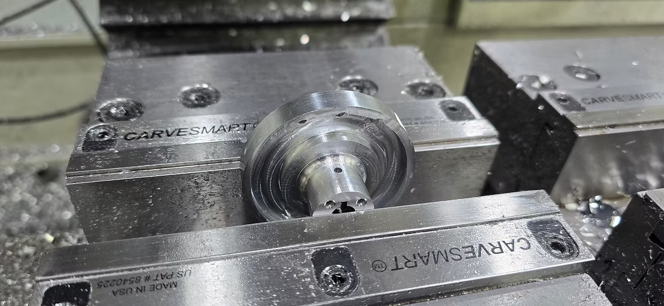
You may notice that I have broached the inner diameter of the spindle - this helps greatly with alignment, by placing a small drill bit in the broach and resting it on the vise jaws, you align the part vertically for drilling.
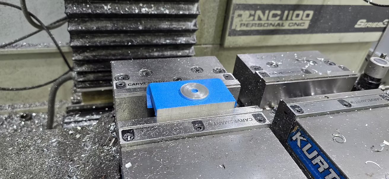
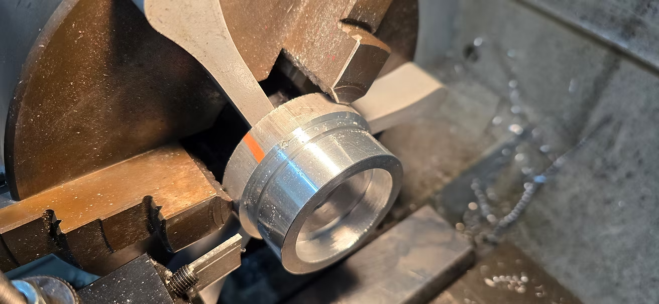
Moving on to the J3 Tension ring, a pretty simple part but with some unique challenges in terms of machining.
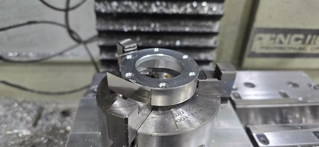
I opted for a slightly different approach this time, I turned the OD on the lathe from a cylinder then drilled and rimmed the center hole (8mm).
Then, using the painter's tape/CA glue method, I was able to hold the part to drill the 4 features and bring the part to thickness with a light pass with the fly cutter:
13 replies
Pierre-Alexandre Girard
As per last time, I have opted to make the base a solid piece of 6061 aluminum (and close the bottom, to prevent dust/dirt into the J1 belt). I have modified the electronic enclosure to attach to the base with 2 M4 machine bolts.
J0 Base OP1, machining of key faces and features:
J0 Base OP2 (removing the "hat"):
I had to machine first a jig to hold the base from below