

AR2 from switzerland
Hi there 😉
I finally pulled the trigger, can't wait to build it !
Thank you Chris for all your work and sharing it, It's awesome.
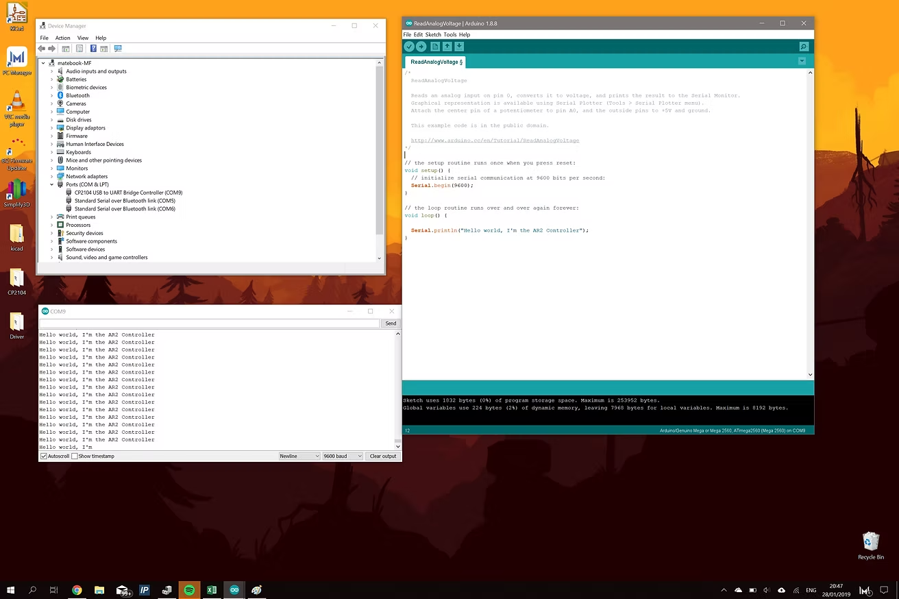
Meanwhile I'm printing plastics parts and working on the controler.
I plan to build something similar to the smoothiebrainz CNC controller I made a few years ago:
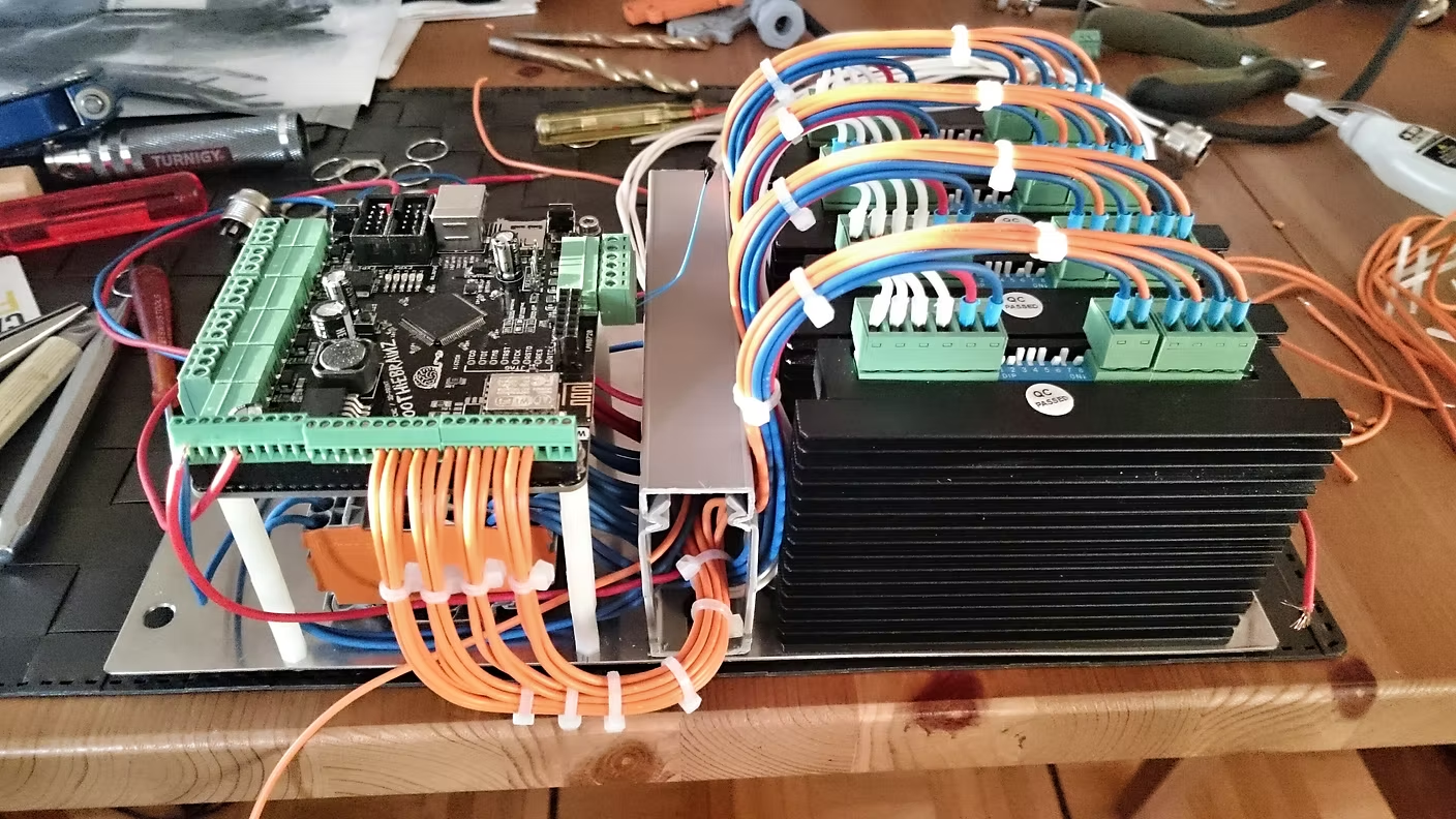
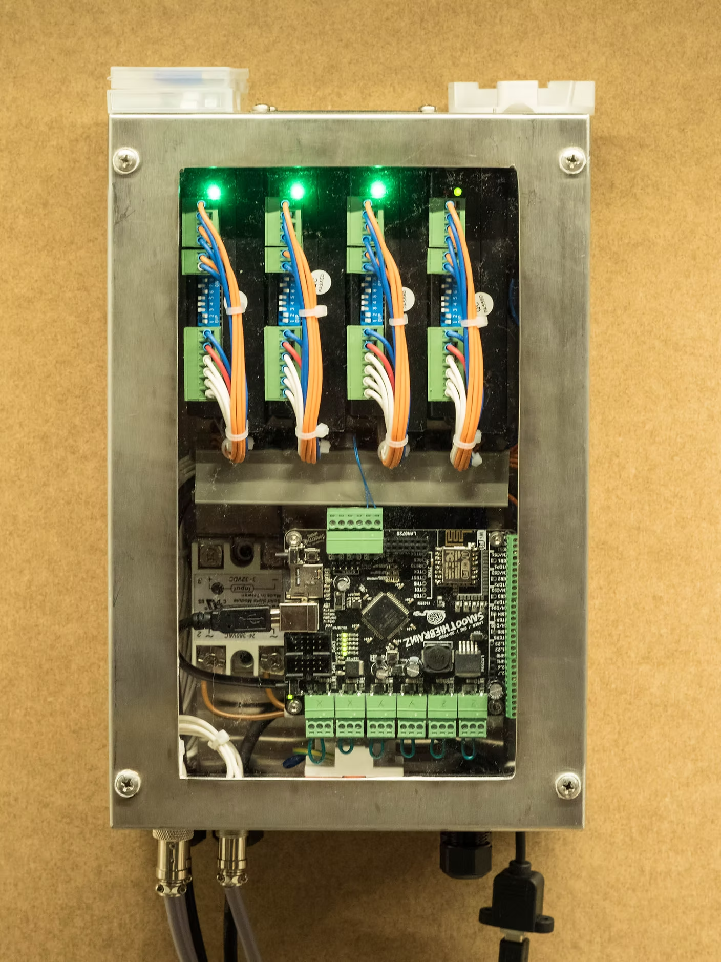
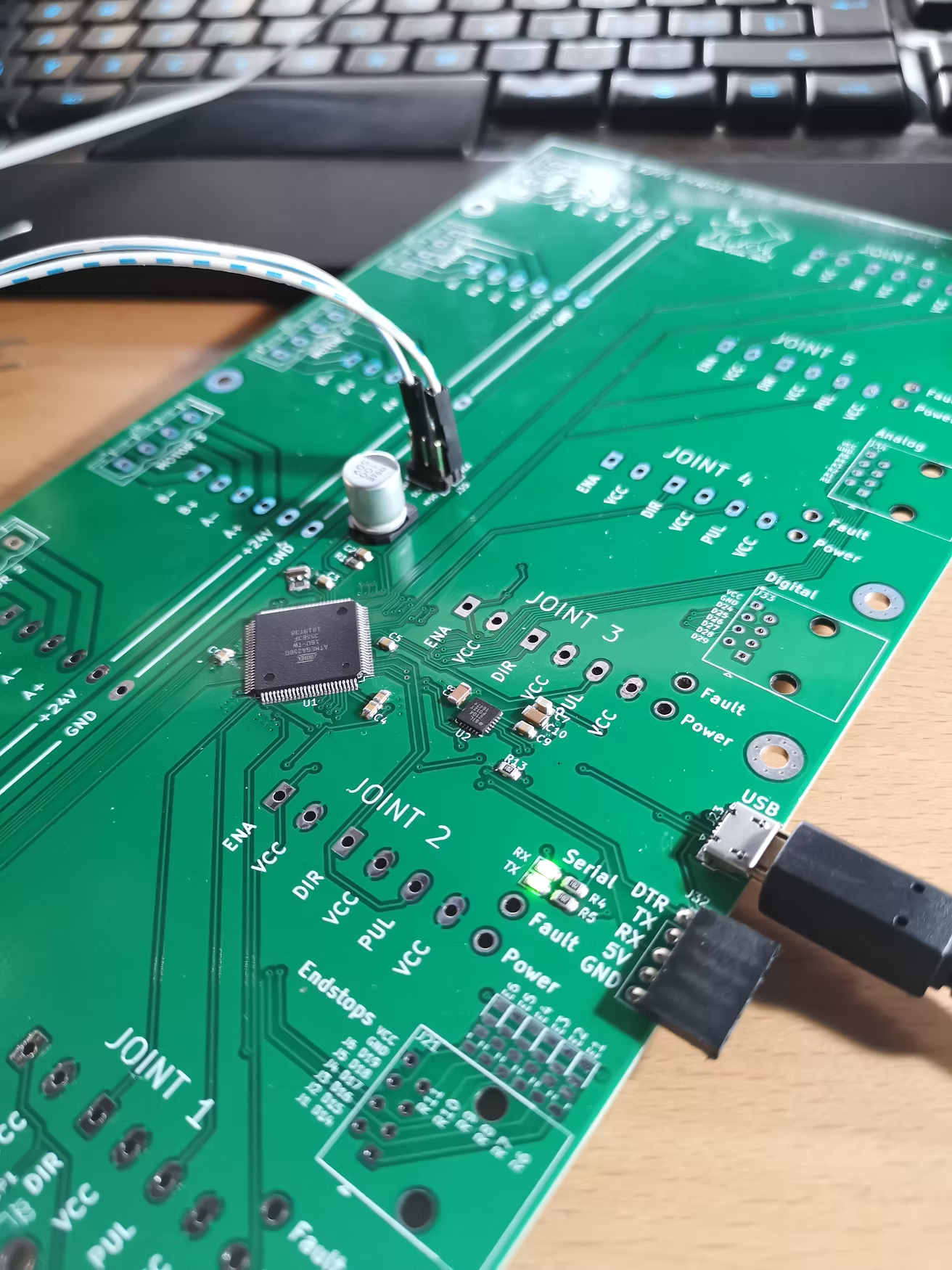
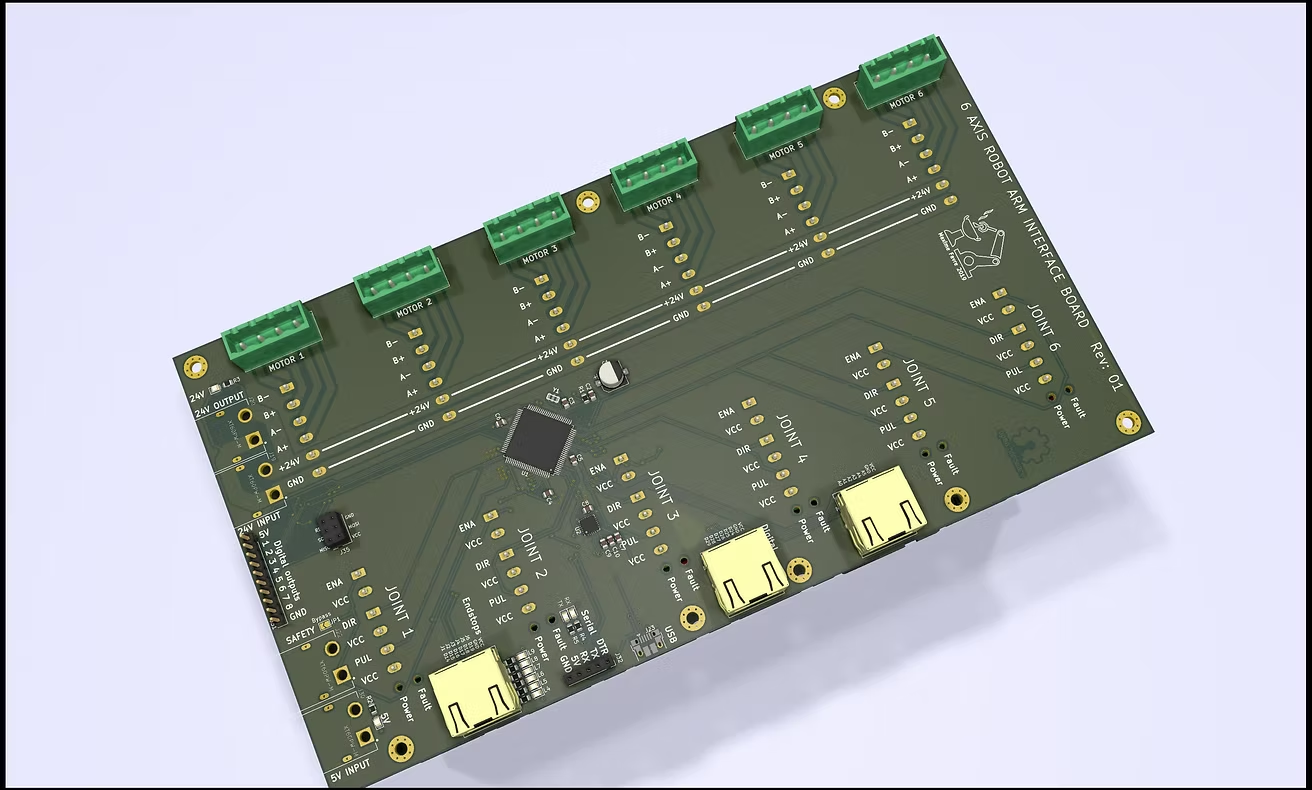
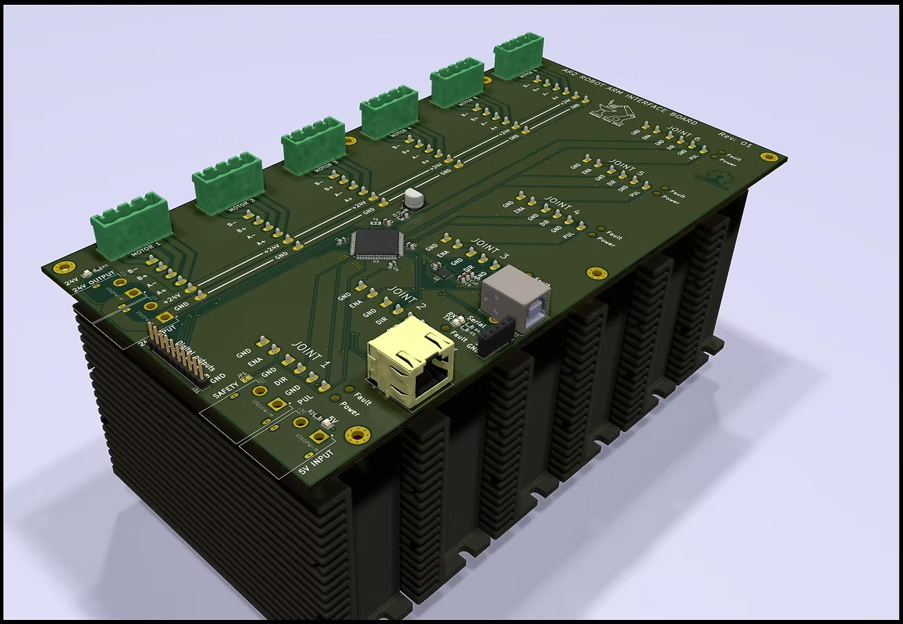
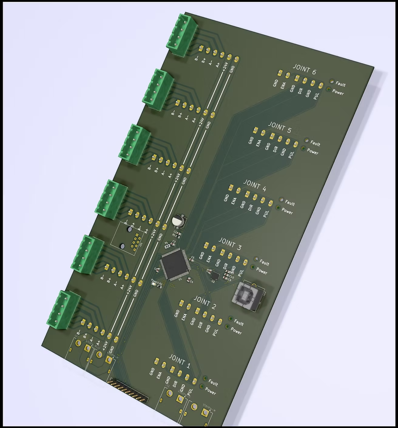
But the big plan is to connect almost everything with a single top PCB. Pins will be soldered on the bottom and screwed in the driver's connectors.
I can either put an arduino footprint or mount a mega2650 directly on the pcb. Not yet decided but I have everything in stock so...
Early WIP:

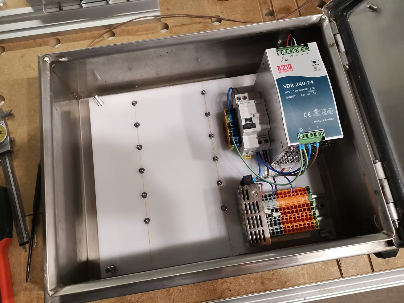
How is the heat generation on the "recommended" enclosure ? I might add fan(s) if I go compact.


favre
I'm so glad that your thinking of using Trinamics. I was also thinking the same when I first saw your design. Do you follow Marco Reps on youtube?
I wonder if limit switches are necessary with the trinamics current sense back shown in his video here.
Do you think an HDMI cable could work? OR DVI? I have been reading that in premium HDMI cables that the strands are paired and sub wrapped by AL as pairs then externally wrapped by braided steel or AL. Furthermore premiums can have 26 or 28 AWG which might be able to handle the current. 2 amps roughly at 26 awg. https://www.powerstream.com/Wire_Size.htm I haven't dived into the typical current draw for this arm design using the motors from the stepper online kit, so take that with a grain of salt.
Also I am a big fan of raspberry pi. Any interest in model 3b+?
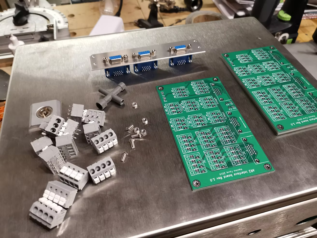
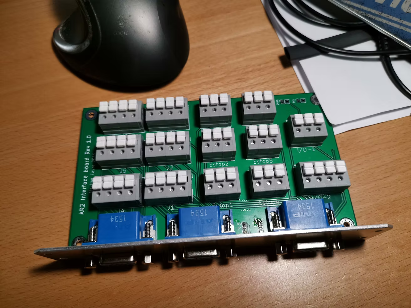
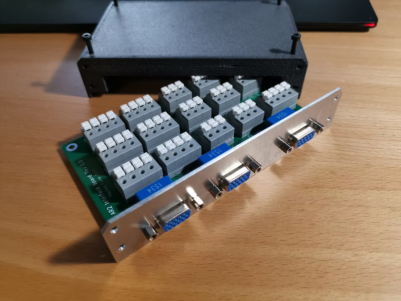
Here are the source files for the PCBs projects:
Controller shield:
https://drive.google.com/drive/folders/1BVWQ9XtNRVI-LLkeI67GsTA8-qUJy9d6?usp=sharing
! Require reflow oven SMD soldering and some arduino knowledge to flash the bootloader
BOM and 7th axis version coming soon
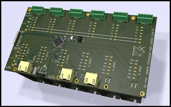
Robot interface:
https://drive.google.com/drive/folders/1DC262n13lVaJyhVmGSyD9pbmnmeG-PZu?usp=sharing
SMD soldering are optional status leds, doable by hand.
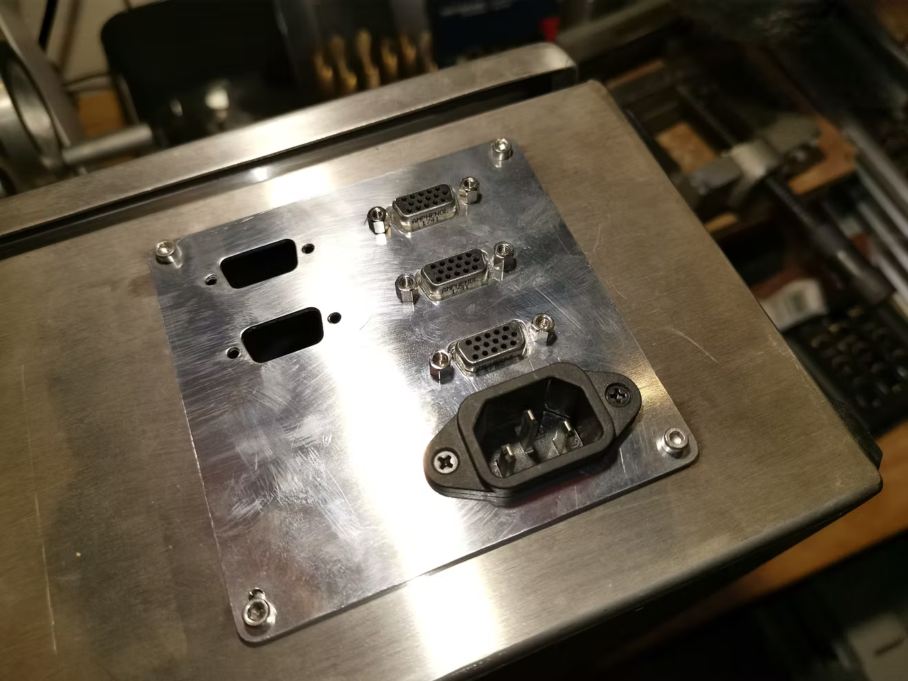
Use VGA connectors and wago 804-103 & 804-104
3d printed housing coming soon.

I ordered 5 pieces of each, used 1 and will spare 1 "in case of" so 3 sets are available. I don't intend to make any money of them, they're just better being used than taking dust in a drawer. I gladly do the SMD and flashing magic, the other components are on your side.
Meanwhile you can order the boards yourself by uploading the zip on the gerber folder on JLCPCB or any other pcb maker.


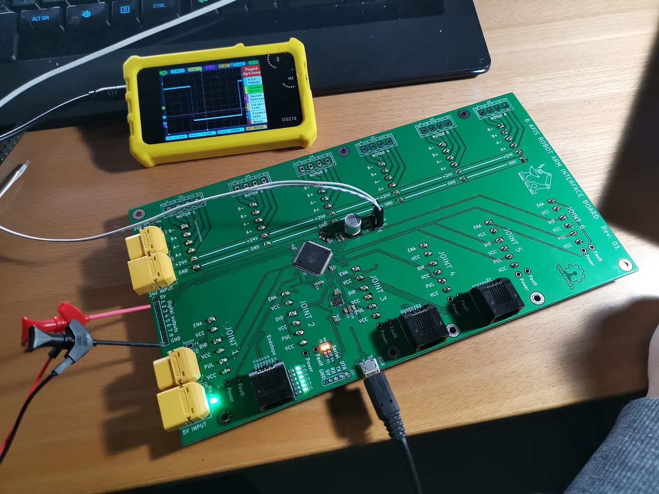
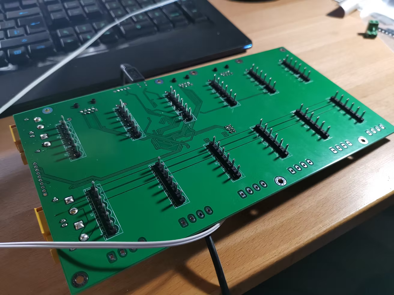
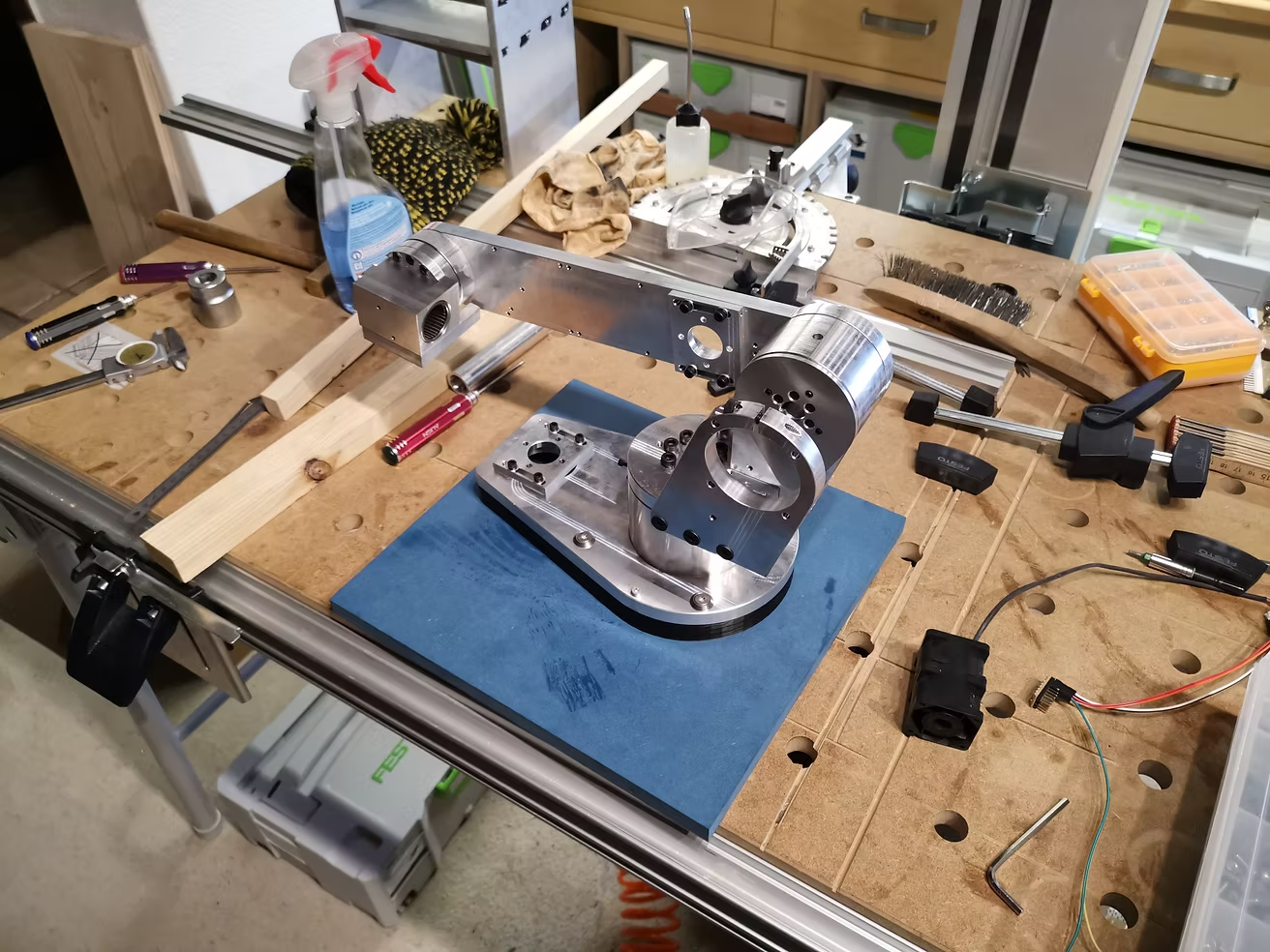
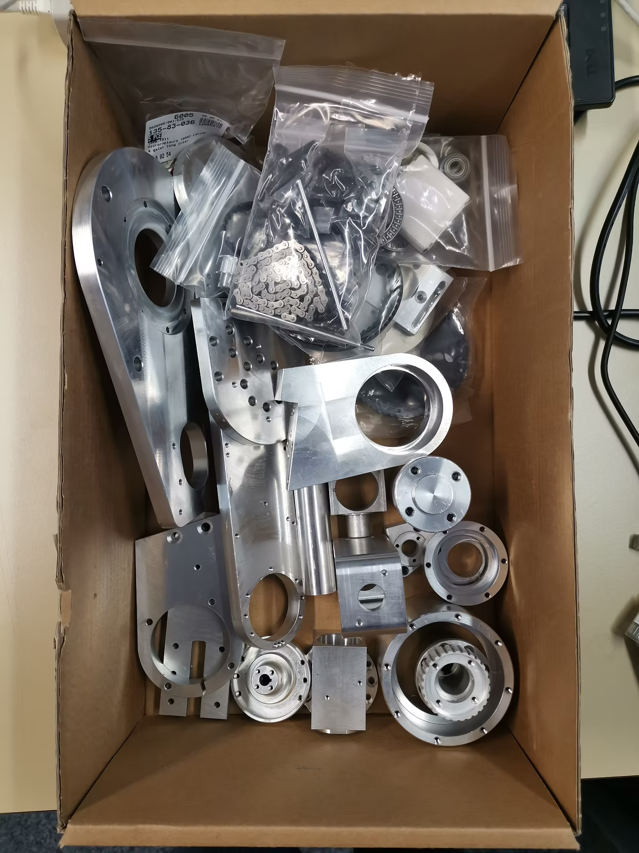
The stepper aren't here but I did what was possible without them. It went pretty well, great job Chris ! Those aluminium parts are really nice.
2 remarks:
- J5 HOUSING: holes for the 3mm rods were drilled at 2.7-2.8mm, I re drilled them to 3mm.
- J6 HOUSING SINGLE PIECE: None of the M3 were threaded but it wasn't a big issue 😉
Meanwhile some progress on the controller: put the cnc to work:
New PCBs should be here monday 😉
Now I'm just hoping OMC can get the missing stepper in stock and post my order before chinese new year holidays 😐
22 replies
rochmesa
Hi.... totally dismantled the CNCCS prototype. Many of the parts are the same as used on the current builds, so I decided to do a new build from scratch so that I could utilize these parts. On this build I am going to go with aluminum on the plate material. My goal is to do this without any special machining gear. IE pretty much using a drill press. Before I get started I wanted to show you my layout since you will see much of it in the background of this build.
turnkey pcb assembly (http://www.7pcb.com/)