

AR3 Control Box
Finally, after more than 3 years I have essentially finished the control box. Still to wire up is the second controller and the wiring for the air solenoid gripper control.
Still some work to do on the arm itself. I was doing a number of the parts in PLA-CF but lately Carbon Fibre filament is starting to look like asbestos. Which is too bad because it prints so nice and is so strong.
I do have a question. The AR4-MK3 HMI interface talks to my Teensy 4.1 which is now powered from the external 5V supply rather than the USB. I can't find anything in the user interface that reports the status of the limit switches. I'd like to be able to actuate them and see if they are correctly interpreted. As in I have them wired correctly.
Or does that feature not exist and perhaps it should?
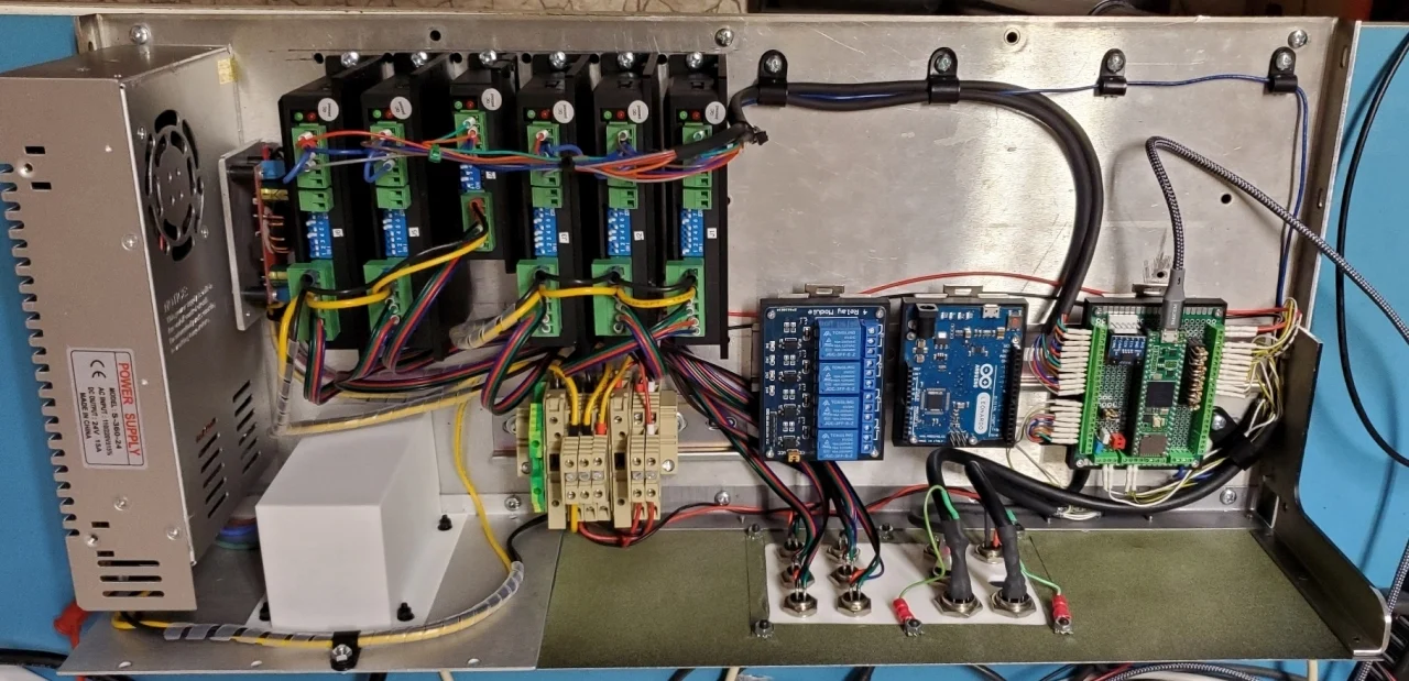
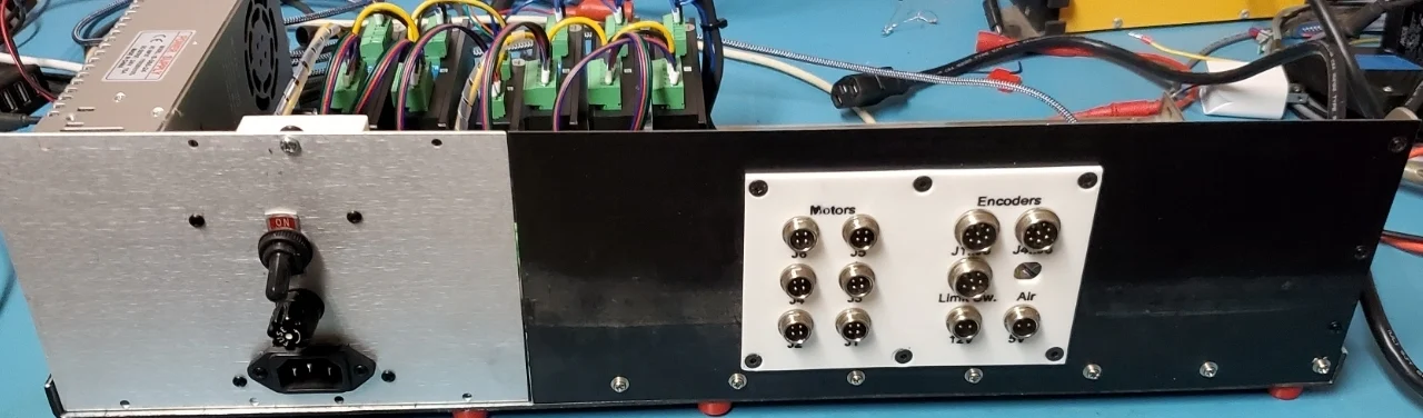

Hello, your control enclosure looks good. Yes there is a program in the HMI folder called test limit switches. If you open the software and load that program it will display the limit switch values. Please review the startup tutorial video on the tutorials tab and there is a bit more info in that video.

Chris Annin Thanks. I was looking for an EXE file which is why I couldn't find it. Testing the limits and two of the encoders helped me find some wiring errors.
I thought I followed the colour codes correctly for the motors but for some reason the J1 motor wanted to go the other way. Just swapped B+/B- and now homing works.
https://youtube.com/shorts/nkengnmAmvY?feature=share
Chris Annin Now 3 axis homing.
https://youtu.be/Hsx7jnIf8lg?si=KV5pV8WKJ5shAH_t
Every motor requires the B+/B- to be swapped to get the arm to move in the correct direction. Now to machine more metal parts as the 3D printed stuff just isn't appropriate. Really wish I had ball screws on my milling machine.
Oh and since I added pull up resistors to 3.3V on the Teensy Carrier board for the home switches I only need two wires for each limit switch and are connected to the normally closed contacts so if a wire breaks theoretically it would stop the machine.
With this little board I can unplug the encoders and switches for service. I've ordered a proper PC board from PCBWay that also has 5 pins for each encoder so the shield wire can be coupled all the way through to the control box.
Chris Annin PCBWay board.
Here's what it looks like. Designed with Protel 99SE. If you want the drawings let me know. I have to test it first though. And the J8 to J10 connectors are wired backwards from my point to point wiring so I have to redo the connectors.
The Teensy 4.1 carrier will probably also be laid out as a PC board with the pull up resistors and I'll add optional differential receivers for the AR4 Motors.