

J2_MotorSupport
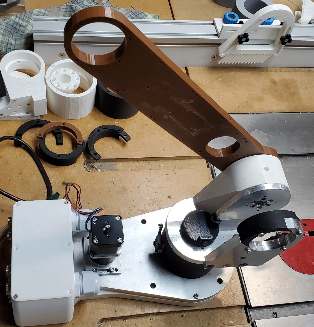
Finally finished the milling on the modified J2 MotorSupport bracket. I started and had all the holes drilled and counter sunk for the original AR3 version.
But then the AR4_MK4 showed up and I like the idea of not taking apart the motor planetary drive to mount it. But the AR3 J2 motor is no longer available and the AR4 J2 motor is larger in diameter and longer. So the 3D printed version didn't fit my AR3 J2 motor.
So back to Alibre to first create the slot to lift out the motor and then design from scratch the inserts to be 3D printed.
I still can't get really nice finishes on the edges with my mill. Not sure if it's the cutter, the speed or backlash but at least it's done. Now to find a piece of 1.75" thick aluminum to replace the 3D printed piece which has no strength.
Oh and the drawing for the J2 Tension Ring was incorrect so I made one that is too thick. Have to thin that down to 3mm so there's better clearance for the J2 motor. The arm is 3D printed just to give me a feel for size. I have a piece of 1/2" plate for this.
Hard to believe I started this project 3 years ago.

Looks good. On the J2 tension ring what drawing was incorrect? was it the old .pdf drawing I had posted on the old website or is there an issue with the model - Id like to make sure I fix this for anyone else.

The pdf. The clue should have been that the dimension arrows didn't match the drawing thickness.
The STL file shows, if sliced with 0.2mm layers, that it creates 15 layers so that is 3mm.
My own Alibre drawing from 12SEP2024 does show it as 4mm but I likely wasn't paying attention to that when I milled it from stock I had on hand. I will fix the AD_PRT file extrusion to be 0.118" (3mm).
There. My J2 Tension part is now 3mm thick. Two inch face mill with 4 carbide cutters for aluminum. Ran it at 2800 RPM and 5 IPM. Depth of cut 0.025" per pass running a simple G-Code program to go back and forth across the part at Z==0.000. Then lower it 0.025", set Z to zero and run the program again. Here's a short 46 second video showing a small part of this.
https://youtu.be/YklUHN2TScw?si=oepG5PqEKPydfONT
Another question. The J3 spindle retainer doesn't appear to be in the photo of all the aluminum parts. Or else I'm just not seeing it. Is it steel or is it aluminum?
Oh and here's a link to a short video where I'm using my Electronic Lead Screw's internal stepper driver to move the J1 axis. This was back in December when most of the parts were plastic. But still it shows how well and smoothly it moves.
https://youtu.be/UoUFpkyuVEM?si=eOIGDhlEtit1WcEs
My ELS was designed to replace or augment the gears used for threading on older metal lathes.