
PaMiLoCELL **#04** – Stepper Motor Wiring
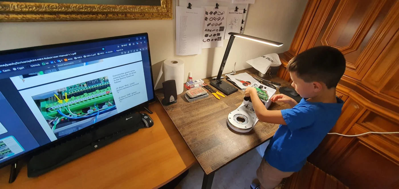
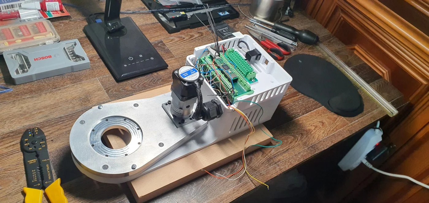
The AR4-MK5 wiring phase is progressing, with particular attention to the J1 stepper motor, digital drivers and control architecture inside the robot’s compact electrical cabinet.
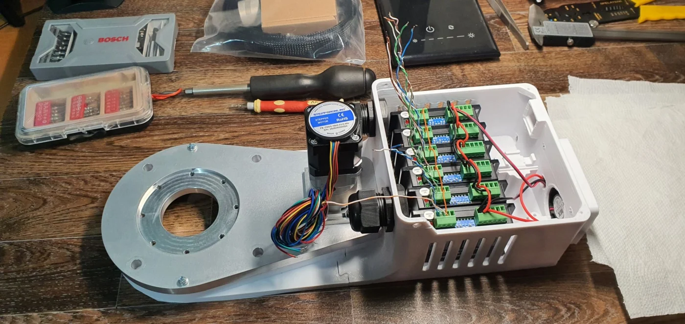
The ground floor of the micro-cabinet is dedicated to the digital stepper drivers. Each driver effectively interfaces two different domains:
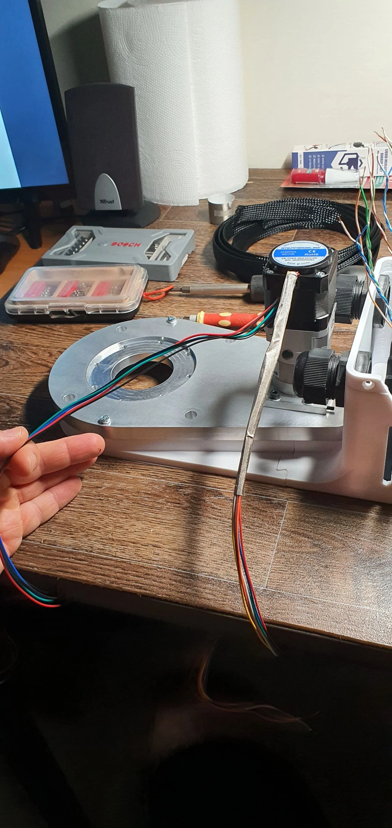
Power side: supplies the controlled phase currents to the stepper motor windings. Correct identification and connection of the motor phases — A+, A−, B+, B− — is essential for proper torque generation and rotation.
Command side: receives low-power control signals such as PULSE, DIRECTION and ENABLE from the controller. These signals define when the motor moves, in which direction and whether the driver output stage is enabled.
This separation between power wiring and control wiring is an important concept in the robot architecture: the driver acts as the interface between low-power digital commands and the considerably higher motor phase currents.
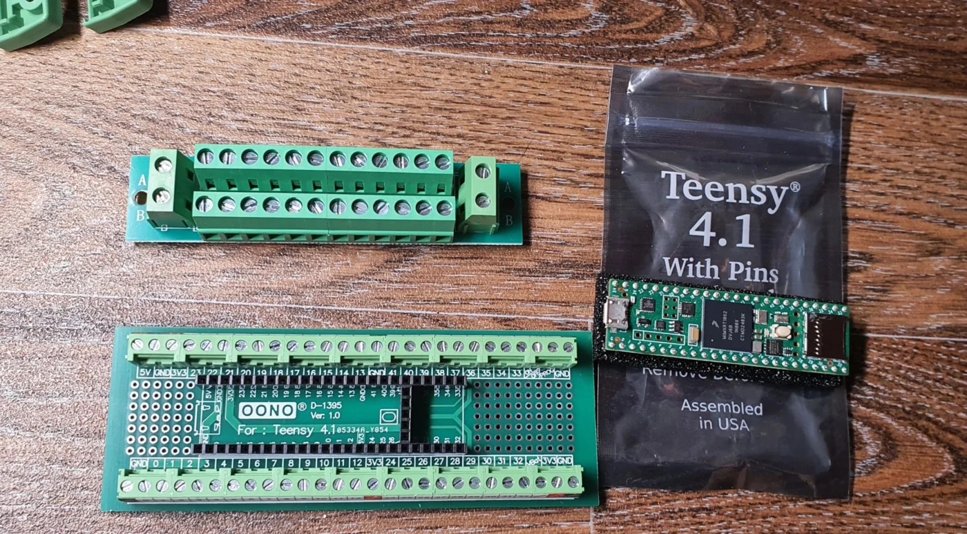
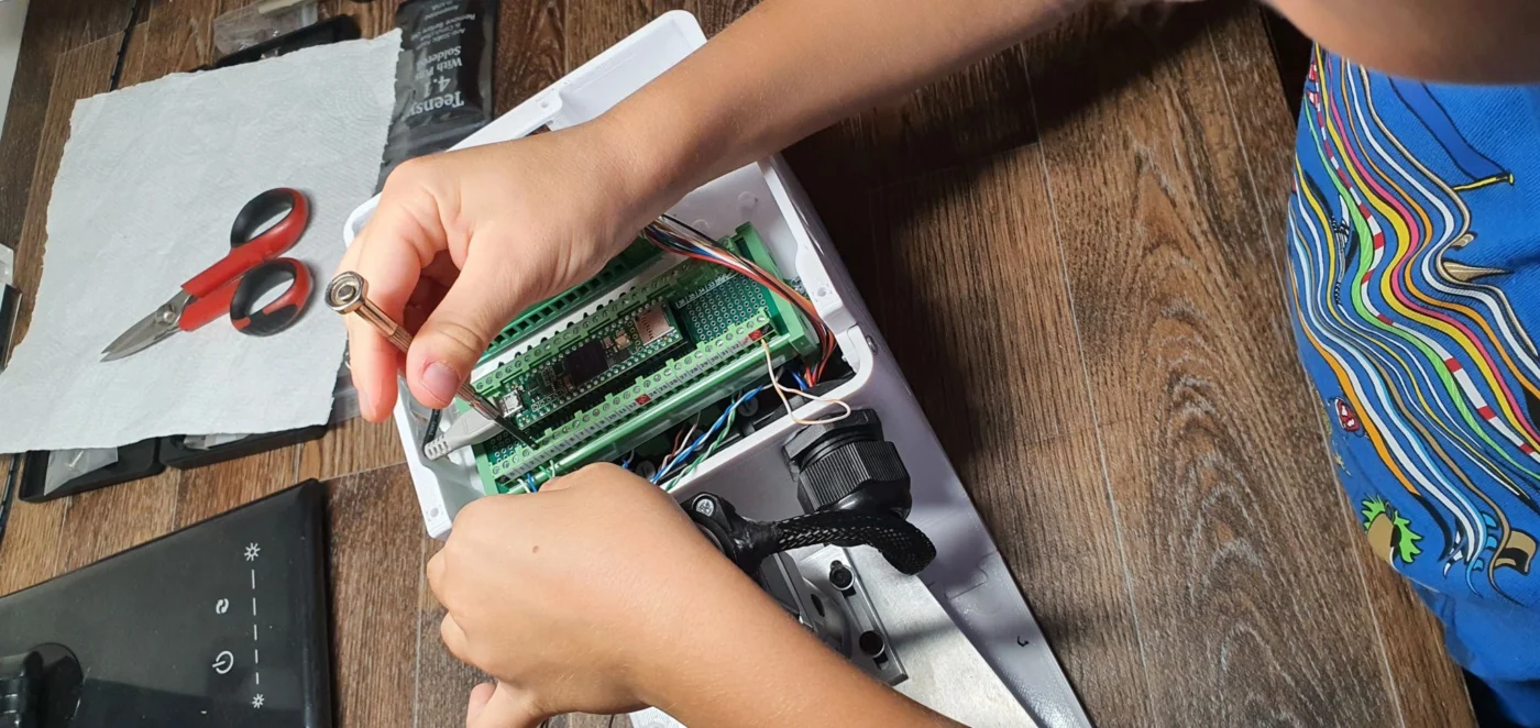
The first floor, immediately above the drivers, is dedicated to the Teensy 4.1 control board. The Teensy is connected to the digital drivers for motion commands, to selected motor feedback/sensor wiring, and will provide the interface toward the external PLC through Modbus RS-485.
The resulting control chain can therefore be summarized as:
PLC → Modbus RS-485 → Teensy 4.1 → STEP/DIR signals → Digital Drivers → Stepper Motors
During assembly, some practical wiring lessons also became clear. Small details can have a significant impact on reliability:
When stripping thin conductors, even a small nick in the copper can create a fatigue initiation point, especially where the cable is repeatedly flexed.
Moving sections should use stranded / continuous-flex conductors whenever possible, rather than rigid solid-core wires.
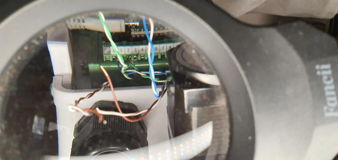
With screw terminals, the conductor must actually enter between the clamping plates. A wire can appear correctly positioned while remaining outside the clamp.
A simple pull test after tightening each terminal is an effective verification step.
Ferrules can improve termination quality for very small stranded wires, provided that the correct size is selected.
Some encoder conductors available on the J1 motor are not required by the standard AR4 configuration, showing the importance of understanding each signal before cutting or terminating the cable.
This phase is not only about completing the wiring. It is also about understanding how power electronics, motion control and communication layers interact inside a compact robotic system.
Next step: complete the internal wiring and progressively validate the control chain from Teensy to the motor drivers.
#PaMiLoCELL #PaMiLoLAB #AR4MK5 #Robotics #StepperMotor #MotionControl #Teensy41 #Modbus #RS485 #IndustrialAutomation #ElectricalEngineering #RobotControl