


Hello,
I purchased the AR3 kit a few months ago, along with a Teensy 4.1 and CUI AMT103-V encoders from Arrow Electronics.
When I try to run the motors individually with the encoders connected, I consistently encounter a “motor collision” error. I am using the AR4 HMI Interface 3.0 software (.exe).
I should also mention that I was unable to source the Molex connectors in my country, so I used jumper wires for the connections instead.
I would appreciate any suggestions or insights on what might be causing this issue.
Thank you.

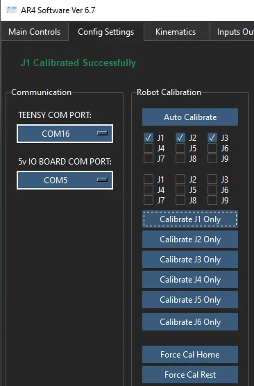
Finally got the ESTOP button installed. Interesting. If I hit ESTOP while Autocalibrating the system does indeed stop.
Once I release the ESTOP the 6.7 user interface is now locked and needs task manager to kill it.
What are the second set of J1..J9 check boxes for? If I click on Calibrate J1 only the second set doesn't need to be checked for J1. Auto Calibrate works fine with just J1..J3.
I'm using this on my AR3 and since I'm keeping the single ended encoder cables physically separated from the stepper motor cables. One for each side of the motors.
The problem is that they butt up against each other and although I could split them so they don't touch then it requires two tie wraps.
So instead I converted the STL file to a STEP file, trimmed the ends and printed them Now I can use one original and one shorter new version together and they don't touch. (Or just two of the newer ones). I've renamed it AR3MotorBracket since I'm using this on the AR3 arm not the AR4 and on more than one joint.
Finally, after more than 3 years I have essentially finished the control box. Still to wire up is the second controller and the wiring for the air solenoid gripper control.
Still some work to do on the arm itself. I was doing a number of the parts in PLA-CF but lately Carbon Fibre filament is starting to look like asbestos. Which is too bad because it prints so nice and is so strong.
I do have a question. The AR4-MK3 HMI interface talks to my Teensy 4.1 which is now powered from the external 5V supply rather than the USB. I can't find anything in the user interface that reports the status of the limit switches. I'd like to be able to actuate them and see if they are correctly interpreted. As in I have them wired correctly.
Or does that feature not exist and perhaps it should?
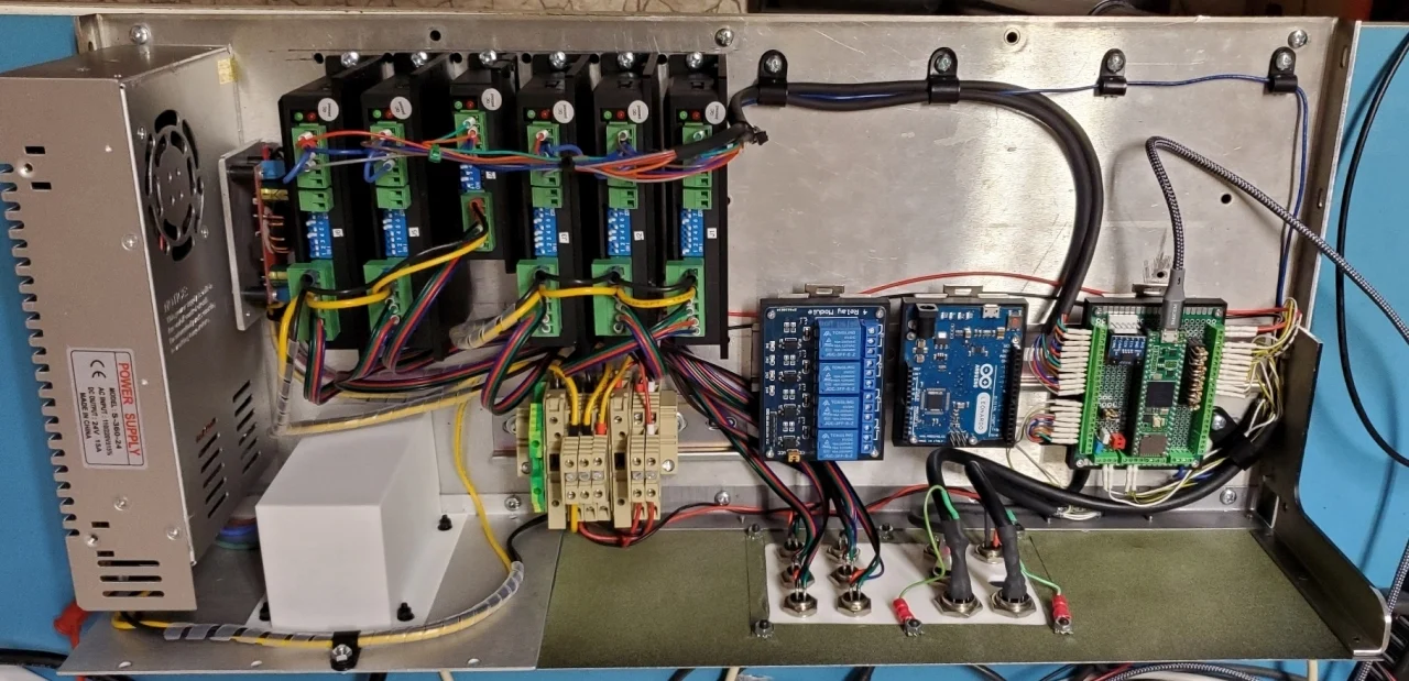
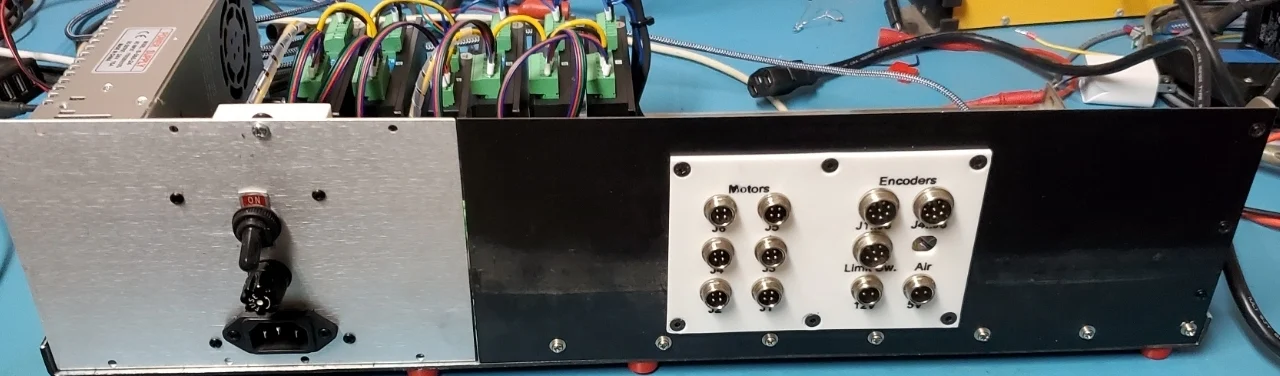
I've attached an initial revision of my control cabinet and how I'm going to put mine together. Since I'm using the Teensy4.1 and the latest AR4-MK4 software I will likely also wire in the support for MODBUS. Especially since I have the software tools from https://www.modbustools.com/ for both master and slave. But I also want to add CAN bus support so the drawing shows how I'd use pins 30,31 (CRX3, CTX3) and switch the J5,J6 limits to 32,33.
The problem is that I see in the newest Teensy4.1 code that these pins are assigned to J8 step/dir. If I switch the declarations in the Teensy4.1 sketch and remove references to J8 will that confused the HMI software running on the PC?
I'm building the AR3 that will use the Teensy 4.1 and the AR4 software and inexpensively as possible but not totally 3D printed.
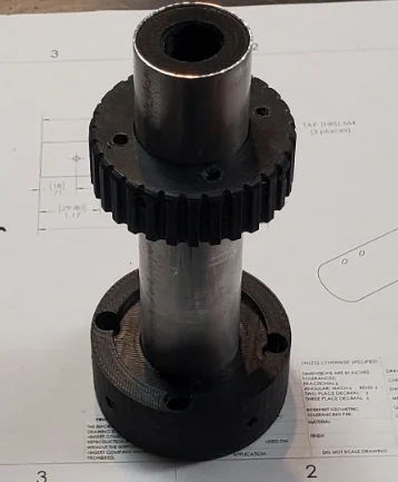
Buying the J4 Main Shaft as a long piece of stock aluminum was too expensive. Then I stumbled on some folding lawn chairs that used 1" OD aluminum tube. Problem is that it's really thin wall and likely even just trying to drill it may compress it out of round. As it is it turns nicely in the bearings and the rest of the parts are all a friction fit onto it.
So what to do? Easy. 3D print an inner liner that is a slip fit into the tube and has a 12.7mm hole down the middle for the joint lead screw. I'll epoxy it in place and then I can easily hold it and drill/tap the 3 holes.
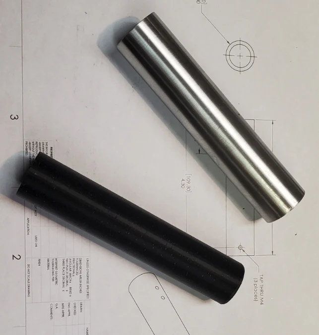
Finally finished the milling on the modified J2 MotorSupport bracket. I started and had all the holes drilled and counter sunk for the original AR3 version.
But then the AR4_MK4 showed up and I like the idea of not taking apart the motor planetary drive to mount it. But the AR3 J2 motor is no longer available and the AR4 J2 motor is larger in diameter and longer. So the 3D printed version didn't fit my AR3 J2 motor.
So back to Alibre to first create the slot to lift out the motor and then design from scratch the inserts to be 3D printed.
I still can't get really nice finishes on the edges with my mill. Not sure if it's the cutter, the speed or backlash but at least it's done. Now to find a piece of 1.75" thick aluminum to replace the 3D printed piece which has no strength.
Oh and the drawing for the J2 Tension Ring was incorrect so I made one that is too thick. Have to thin that down to 3mm so there's better clearance for the J2 motor. The arm is 3D printed just to give me a feel for size. I have a piece of 1/2" plate for this.
Hard to believe I started this project 3 years ago.
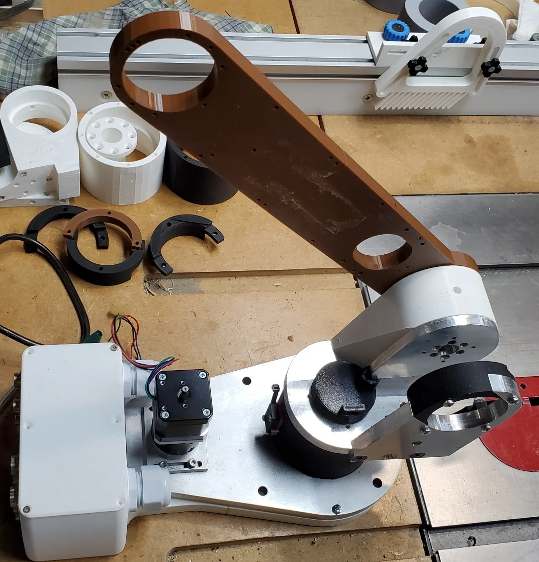

Hello everyone,
I bought a recommended printer – Anycubic Kobra 2 PRO – to print the 3D parts. I saw that the AR4 MK3 manual explains that, among other things, the J1 Base Plate and J2 Arm should be printed in 2 parts; however, I couldn’t find the .stl files for these 2 parts in - Large Parts Split for Smaller 3D printer. (I downloaded the .stl files from the official page at https://anninrobotics.com/).
Does anyone have any suggestions about this?
(It’s important for you to know that I’ve already printed several other parts—more than 32 pieces—including some that were split into two parts)

Hi everyone.
Is it possible in the AR4 software to make the “Teach New Position” button send a position request to the Teensy — but based on the encoder readings?
I mean that the program would convert the encoder feedback into coordinates as new points, without any physical motion commanded by the controller.
I’m building a robot with a “touch” (freedrive) function. I already have a secondary program that switches the servos into torque mode and assists manual joint movement with anti-gravity, just like in cobots. The servos output quadrature A/B encoder signals.
It seems to me that the AR4 program only checks the position from the encoder and compares it with the programmed value.