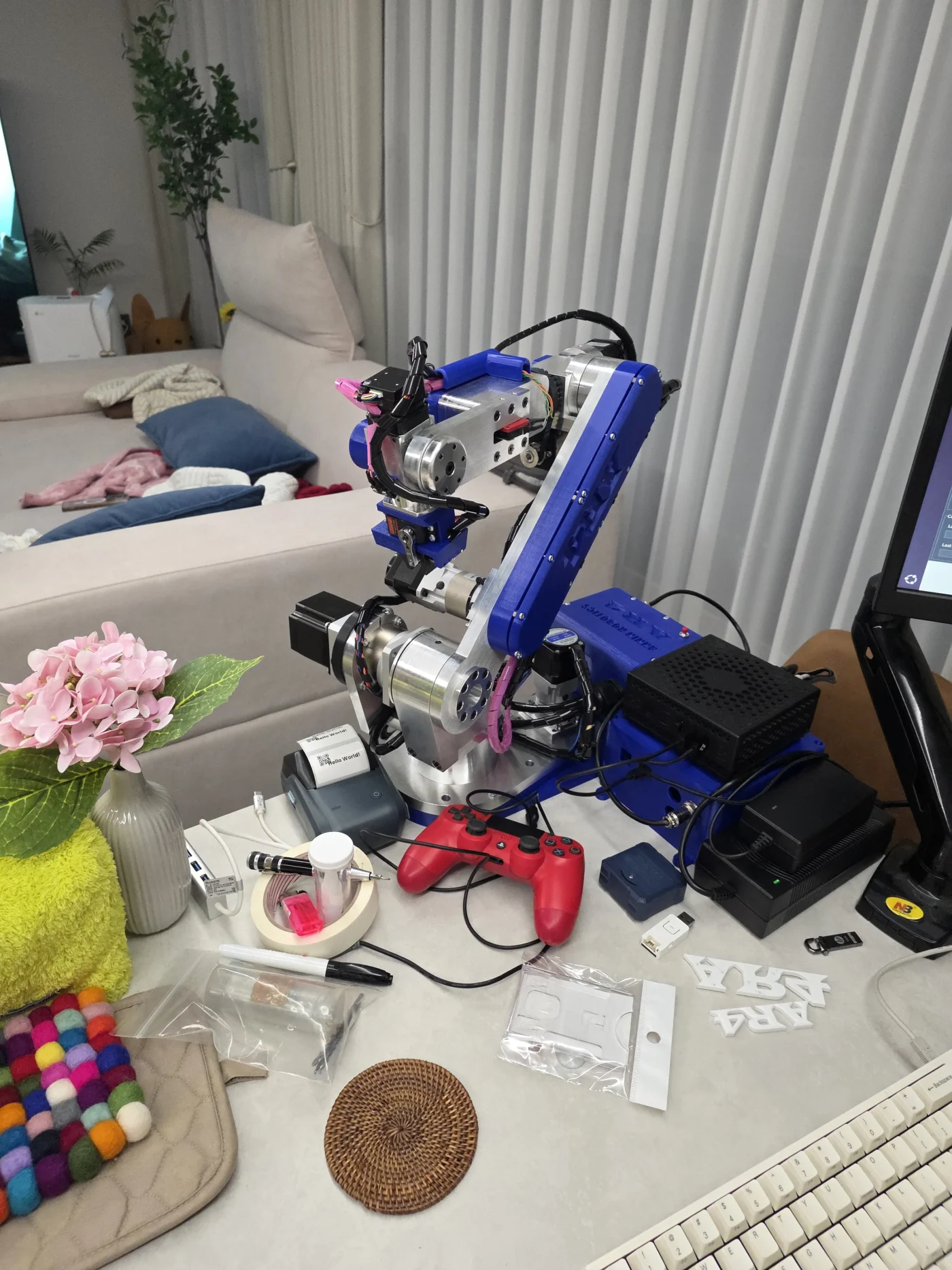

If we look at the AR4-MK3 STL files for the J2 Turret Housing and the J1 Turret Platform, they don't match the PDF 2D drawings which are only available on the original AR4 page.
Will these 2D drawings ever be updated to match the newer models?
For example I notice that the J1 Turret Platform is now wider than the one for the AR3. The J2 Turret Housing is now offset from the one for the AR3. Yet the drawings still show more mounting holes and a curved cutout rather than flat.
After a few years absence I've restarted my project and I'm wondering if the software will also reflect the shift in position of the J2 ARM.

A student project wants the arm to be able to move through 360 degrees. But it would seem that you don't want the arm to operate over the power/controller unit? Any pointers to documentation much appreciated.

A few questions for the group:
I have converted J1, J2, and J4 to magnetic hall effect calibration sensors and they work well on V6.1.
I want to use an xbox controller for training the robot arm and am thinking of upgrading to 6.3 if it has better xbox control. But before I do, I need to change the three sensor active states from low to high.
1) What lines in 6.3 control the home input signal?
2) Is there a need to move to 6.3 to use the xbox controller or does it work fine with 6.1?
Thanks!

I'm installing until the process of inserting J2 Motor into the Spindle. I've put the shaft into spindle for a quarter but i can feel the backlash from the gearbox when I rotate. I'm quite sure i'm not break any gear when i disassemble and re-install the gearbox.
I'm just curious is this backlash is normal or not? Will the backlash be disappeared when there is power supply to motor?
I would like to re-confirm this gearbox is in good condition before i fully insert the shaft into the spindle. Because it will be very difficult to remove it later.
I'd like to know the code to return the robot to its starting point. Is there a serial transmission code that returns one axis at a time when the axis loses its position due to a collision while driving one axis at a time?
The video shows a circle moving, but when I try to do it myself, it moves strangely. It would be helpful if there were a video and example robot drive code attached.

In the vision tutorial, there are references to a gripper pointer tool stored in the miscellaneous folder. I am not able to locate that folder anywhere. Is it possible to include that particular STL file in the main bundle (or does someone have a copy)?

Hi community,
I’m very excited to experiment with the new AR4-HMI build and currently have version 6.3.1 running from source on Ubuntu 22.04.
Since I’ve gotten older versions (4.xx and 5.xx) running on my Mac M1 (Apple Silicon, ARM CPU) — which is actually my main machine for coding — I recently discovered that the GitHub source files are not compatible with my laptop’s architecture.
When running python AR4.py after completing all setup steps, I get the following error:
Traceback (most recent call last):
  File "../x/AR4.py", line 167, in <module>
    import ARrobots.robot_kinematics as robot
ModuleNotFoundError: No module named 'ARrobots.robot_kinematics'
I understand that the build relies on .pyd and .so library imports. As Chris Annin explained, these files are similar to Windows .dll files and bundle specific functionality. The downside is that they need to be precompiled for each architecture. From the files in the ARrobots folder, I can see that the libraries were compiled for Linux x86_64 (Python 3.11 and one for 3.12) and for Windows x64.
Since I’m running ARM, I’m wondering if anyone could help me build the .so/.pyd files for Mac M1.
Am I correct in assuming that everything needed for the build is in the ARrobots/src folder?
I’m really looking forward to your help!
Best regards,
Justin
P.S.: I also have Windows for ARM installed on the same system, and I can confirm that the program runs when using the downloadable .exe from the download section. Does this mean the .pyd file is both x86_64 and ARM compatible or is this the windows conversion layer at work; going from ARM instructions to X64?
Does someone here have STL files for a base with a slightly larger housing? That could make wiring and debugging easier. The split housing part of the base is 190mm, but it could probably be increased to 210mm for most standard 3D printers (at least for mine).
Hi Chris Annin,
for some reason some of the feeds I have been posting are missing from the forum..
The feed AR4 6.3 Vision error & Xbox controller Linux specifically is still showing up in my private section under comments but can't be accessed anymore. This neither works from the "comments" space nor when searching for the post.
Is this intentional?
Looking forward for a reply :)
Lg
J

Thank you. I finally finished assembling the AR4 MK3 robot and will be able to perform the initial test run this weekend. I have one question. After all joints complete the auto-calibration process, I would like the robot to move to and rest in a predefined standby position as shown in the image.
Should I simply save that position and command the robot to move there, or is there a better recommended method?

I would also like to know how to turn off the motor power for each joint. I’m not referring to cutting the main power supply, but rather a programmatic way to disable the motors. Is there a method to do this through software control?

I want to configure the program so that the robot stays in a motor power-off state and then performs specific actions according to a scheduled time.