
Mechatronics guide
A Robot Arm for the Mechatronics Lab
Mechatronics is mechanics, electronics, control and software working together. The AR4 puts all four on one bench, with every wire and sensor where students can reach it.
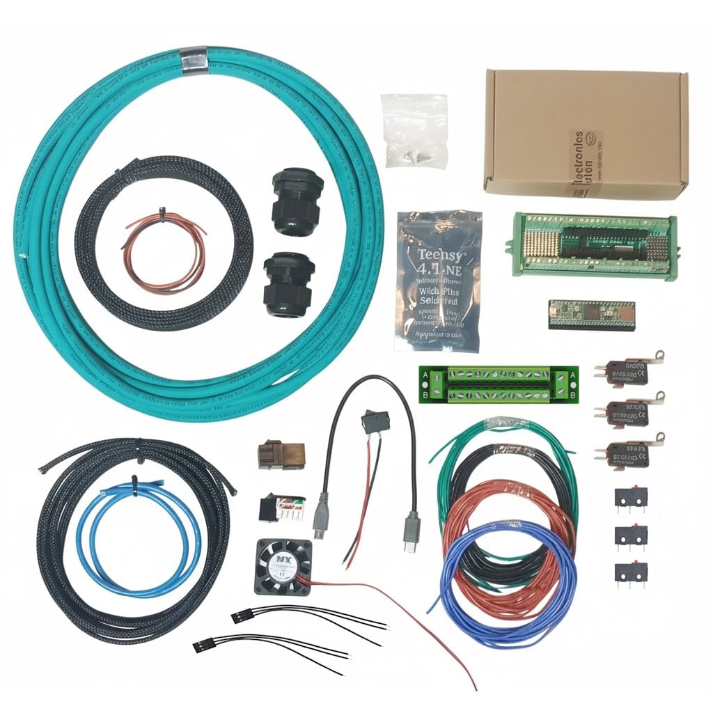
Open electronics
A Teensy 4.1 runs six closed loop stepper axes and up to three more. An Arduino Nano handles 5 V grippers, relays and sensors. A Modbus RS-485 upgrade links the arm to a PLC.
Arm axes
6 + up to 3
Nano I/O
8 / 8 / 8
PLC link
Modbus RS-485
Modbus kit
$16
The subsystems students work with
| Drives | Stepper drivers per joint: DM332T on J1 to J3, DM320T on J4 to J6, set by DIP switch microstep settings |
|---|---|
| Motors and feedback | Geared stepper motors with encoder feedback on every joint |
| Homing | Hall effect sensors on J1 to J3, microswitches on J4 to J6 |
| Motion controller | Teensy 4.1 at 600 MHz running the kinematics, programmed from the Arduino IDE |
| Tooling I/O | Arduino Nano or Mega at 5 V: up to 8 servos, 8 digital outputs and 8 inputs with the Nano sketch |
| Pneumatics | MHF2-8D1 gripper, 24 V 5 way solenoid valve, relay module and a small compressor |
| Fieldbus | Modbus over RS-485 (2 wire, 38400 baud) to a PLC, through an RJ45 keystone jack |
| Power | 24 VDC, 198 W (8.25 A) max |
Lab exercises from the manual
Chapter 8 of the build manual is a ready made troubleshooting lab. Each step has a clear pass condition and a list of likely faults.
- Step 1Jog each motorWith encoders disabled, jog every joint in both directions. A joint that will not move points to motor wiring or the pulse wire; one direction only points to the direction wire.
- Step 2Check the OPTO supplyVerify 3.3 V at each driver's OPTO terminal. A bad connection can cause odd behavior that looks like a software fault.
- Step 3Verify direction and distanceConfirm positive and negative directions, then use an angle gauge to check a 10° jog really moves 10°. Wrong distance usually means wrong microstep settings.
- Step 4Test sensorsRun the limit switch test program and trigger each Hall sensor and switch. Adjust sensor mounts until they trigger every time.
- Step 5Test encodersRun the encoder test, cut driver power, move each joint by hand and watch the counts change.
- Step 6CalibrateCalibrate each joint, measure any error with a digital level and enter calibration offsets.
PLC and Modbus integration
The $16 Modbus upgrade mounts an RS-485 TTL adapter in the base and brings it out on an RJ45 jack. Many PLCs use a simple three wire A+, B− and ground connection. The manual shows a Direct Logic example; the AR4 Python API adds coil and register read and write calls plus wait helpers, so students can coordinate the arm with a conveyor or machine.
Control theory and software
Advanced students can study forward and inverse kinematics with the downloadable DH parameter sheets, plan motion in ROS 2 with MoveIt, or modify the open Python HMI and Teensy firmware. See the kinematics guide and ROS 2 MoveIt tutorial.
Equip your lab
Get a lab quote
Choose kits, Modbus upgrades, grippers and spares, and we email a pro forma invoice for purchasing.
Keep reading
FAQ
Why use the AR4 in a mechatronics lab?
Every subsystem is exposed: stepper drivers, encoders, Hall effect and limit switches, a Teensy 4.1 controller, a 5 V I/O board, pneumatics and a Modbus link to a PLC. Students wire, test and troubleshoot each one.
Can the AR4 talk to a PLC?
Yes. The $16 Modbus upgrade adds an RS-485 adapter and RJ45 jack. The manual uses RS-485 2 wire at 38400 baud and shows a Direct Logic PLC example; the station number is configurable.
What I/O does the AR4 have for grippers and sensors?
An Arduino Nano runs 5 V tooling: the AR4 Nano sketch controls up to 8 servos and 8 digital outputs and monitors up to 8 inputs. An Arduino Mega can be used for more I/O.
Does the AR4 support pneumatics?
Yes. Chapter 4 of the manual builds a pneumatic gripper with an MHF2-8D1 parallel gripper, a 24 V single coil 5 way solenoid valve, a 5 V relay module and any small compressor with a regulator.
What troubleshooting can students practice?
The startup procedure covers checking motor direction and distance per jog, the 3.3 V supply at each driver's OPTO terminal, limit switch and Hall sensor tests, encoder tests and calibration offsets.