
CAD guide
Design Custom AR4 Grippers in Fusion 360 and SolidWorks
A custom finger or tool starts from the arm's real geometry. The AR4-MK5 mechanical model is sold as SOLIDWORKS and STEP so you can design against the flange instead of measuring a finished robot.
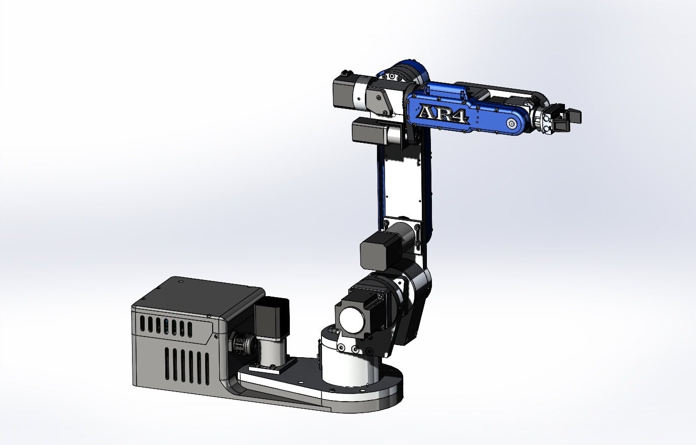
Models for the MK5
The $99 AR4-MK5 CAD models are the SOLIDWORKS parts, a complete SOLIDWORKS assembly and matching STEP files. Design the tool, then build it on the AR4-MK5 6 axis robot arm kit.
Native
SOLIDWORKS
Interchange
STEP
Print files
Free STL
Use
Education, personal
What the CAD download contains
The product page lists every AR4-MK5 component as .SLDPRT and .STEP, plus the complete SOLIDWORKS assembly. Use the assembly to check that a gripper, camera or fixture clears the wrist and the covers.
| SOLIDWORKS | .SLDPRT parts and the full assembly |
|---|---|
| STEP | .STEP of the same components, for Fusion 360 and other CAD |
| License | Educational and personal use. Redistribution is prohibited. |
| Not included | A native Fusion 360 archive. Open the STEP files instead. |
Selling robots, robot parts, or versions based on this work without written permission is prohibited. The full license is on the CAD product page.
Design a gripper in SolidWorks or Fusion 360
- Step 1Open the assemblyIn SolidWorks, start from the supplied assembly. In Fusion 360, import the STEP components and mate your tool to the flange.
- Step 2Match a known gripperThe pneumatic kit follows the SMC MHF2-8D pattern. The pneumatic gripper CAD models thread shares a GrabCAD assembly of the MHF2-8D1, press-in air fittings and two finger designs with rubber pads.
- Step 3Or start from the servo filesThe free servo gripper CAD and print files are the fingers and housing the servo kit does not include. Edit those if you only need a new finger shape.
- Step 4Stay inside the armCount the tool and the part together against the 1.9 kg (4.15 lb) rated payload, and keep the work inside the 629 mm (24.75 in) reach. Published repeatability is ±0.25 mm.
Models for printing versus models for machining
- Cover and spacer STLs for the MK5 are free: AR4-MK5 print files on the downloads page. The aluminum structure is machined, not printed.
- The 3D printing guide covers printing those files or buying a PETG set.
- Ready-made options are the servo and pneumatic gripper kits. Printed fingers are not in the servo kit.
Check the tool before you cut metal
Jog the virtual robot in the HMI with the tool's reach in mind, then confirm joint limits on the real arm at low speed. A finger that looks fine at one wrist angle can meet the forearm at another.
When the shape is done, the same STEP can go to a 3D printer or a machine shop. See G-code on the AR4 if the arm itself will trace a path from the drawing.
The arm
AR4-MK5 6 axis robot arm kit
The combo kit is the aluminum structure, hardware and primary electronics. Add the CAD download when you are designing tools. Every kit option is on robot kits.
Keep reading
FAQ
Do the AR4 CAD files open in Fusion 360 and SolidWorks?
The paid AR4-MK5 CAD download is native SOLIDWORKS parts (.SLDPRT) plus a complete SOLIDWORKS assembly, and the same components as STEP (.STEP). Fusion 360 opens STEP. There is no separate Fusion 360 archive in that download.
Do I need the paid CAD models to 3D print covers?
No. The MK5 STL print files are free on the downloads page. The paid download is the full mechanical model for designing tools, checking clearance and machining parts.
Can I share or sell parts made from the CAD?
The product license allows educational and personal use. Redistribution of the models is prohibited, and selling robots, parts or versions based on the work needs written permission from Annin Robotics.
Where do I get gripper models?
The servo gripper CAD and print files are a free download. A community thread shares GrabCAD models of the pneumatic gripper (MHF2-8D1, air fittings and two finger designs). The build manual shows the MHF2-8D pattern and says you can mount any gripper you choose.