
Wiring guide
Wiring and Soldering the AR4: Harnesses, Connectors, and Multimeter Checks
The MK5 electrical work is a harness you build in order, then prove with a meter before any joint is allowed to run. The manual is the procedure. This page is the map of that procedure and the checks in the startup lesson.
Manual first
Follow the AR4-MK5 build manual, then the startup video on tutorials. The arm you are wiring is the AR4-MK5 6 axis robot arm kit.
Arm logic
Teensy 3.3 V
Tooling
Nano 5 V
Limits
0 V / 3.3 V
Encoders
5 V
Harness order in the MK5 manual
The education page describes this skill as building harnesses, soldering connectors, applying heat-shrink and checking with a multimeter. In the MK5 manual that work is staged: drivers and power in the base, the Teensy and encoder leads, the J6 cable with the harness sleeved, then every wire landed on the terminal blocks.
- Step 1Base power and driversMount the stepper drivers, rocker switch, fan and power wiring. Manual, base enclosure.
- Step 2Teensy and encoder leadsInstall the Teensy 4.1 and breakout in the base and wire drivers and encoders. Manual, controller.
- Step 3J6 cableCut and wire the J6 cable, sleeve the harness, and choose the gripper option before you close the arm. Manual, J6 cable.
- Step 4Land the harnessFeed the harness back through J2 and land every wire on the terminal blocks. Manual, harness.
Connectors and the two voltages
The Teensy 4.1 is the 3.3 V motion controller. The Arduino Nano is the 5 V board for servos, relays and solenoid coils. Limit switches are on the 3.3 V side. Encoders are on 5 V. Mixing those supplies, or shorting either rail to ground, is how boards get damaged. The troubleshooting wizard checks both rails for a short to GND with the Teensy unplugged from its board.
| Limit input, switch open | About 0 V (ground) |
|---|---|
| Limit input, switch pressed | About 3.3 V |
| Driver OPTO terminal | Solid 3.3 V |
| Encoder power at the terminal board | 5 V on the encoder red and black pair |
| Nano tooling | 5 V servos, relays and outputs |
Startup checks with a multimeter
The startup lesson on the tutorials page is for after Chapter 2. Its checks are encoder feedback, every limit switch, jogging each axis, wiring connections, limit-switch signals with a multimeter, and motor direction. Chapter 8 of the manual is the same sequence.
- Step 1Continuity before powerConfirm each conductor lands where the manual shows it, and that 3.3 V and 5 V are not shorted to GND.
- Step 2Limit switchesRun the limit-switch test and meter the input: 0 V open, 3.3 V made. A floating input or a switch that never leaves 0 V will fail calibration.
- Step 3OPTO supplyMeter 3.3 V at every driver's OPTO terminal. A missing OPTO voltage makes a drive look like a software fault.
- Step 4Direction and one jogWith encoders disabled, jog each joint both ways. No motion points at the motor or pulse wire. One direction only points at the direction wire.
- Step 5EncodersCut driver power, move the joint by hand and watch the counts. If every encoder is dead, check the 5 V feed before you replace a sensor.
The same video's firmware chapter starts just after the introduction. Both are linked from tutorials. When a check fails, the troubleshooting wizard walks the yes/no path for homing, collision errors and a Teensy that will not connect.
The Teensy 5 VDC thread
The community post Properly wiring the Teensy, the 5VDC connector mystery is an AR3 build. The control box was wired, continuity was checked, and the software saw the Teensy 3.5, but no joint would jog. The question is whether Teensy Vin and GND should be jumpered to the 5 V aviation connector on page 279 of an AR3 manual. Replies disagree, and one builder describes powering an AR3 Teensy from USB only.
That thread does not document the MK5 base. For an AR4-MK5, use the current manual's Teensy and power figures, then the Chapter 8 meter checks above. Do not add a Vin jumper because an older drawing looked ambiguous.
The arm
AR4-MK5 6 axis robot arm kit
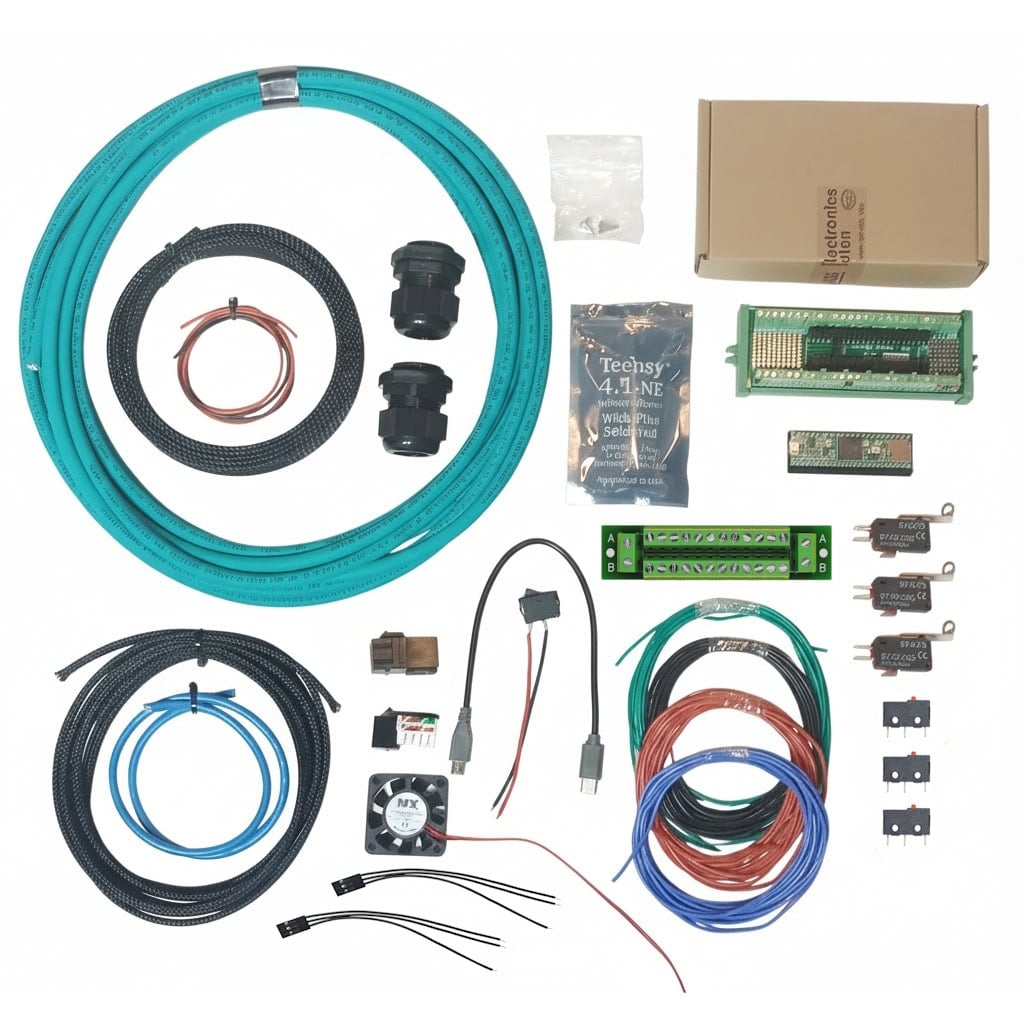
The electrical kit in the combo is the wire, connectors, Teensy and breakout this procedure lands. See the full list on robot kits.
Keep reading
FAQ
Where is the AR4 wiring procedure?
Chapter 2 of the AR4-MK5 build manual builds the harness: drivers and power in the base, the Teensy 4.1 and breakout, the J6 cable, then the harness landed on the terminal blocks. Chapter 8 is the startup checks after the wires are in.
What should a multimeter show on a limit switch?
The troubleshooting checks expect about 0 V (ground) when the switch is open and 3.3 V when it is pressed. Encoders are powered from 5 V. Each stepper driver's OPTO terminal should read a solid 3.3 V.
Why are there two logic voltages?
The Teensy 4.1 runs at 3.3 V and drives the arm. The Arduino Nano runs at 5 V for servos, relays and other tooling. Do not treat those rails as interchangeable.
Does the Teensy 5 VDC thread apply to the MK5?
That thread is an AR3 control-box question about jumpering Teensy Vin and GND to a 5 V aviation connector. Follow the MK5 manual for an MK5. Do not copy an unfinished AR3 experiment onto the current base.